18. MR-J4W2-0303B6 SERVO AMPLIFIER
18 - 32
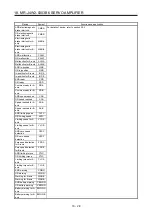
Setting
value
Output item
Description
Setting
value
Output item
Description
0C Feedback
position
(10 V ± 5 V/100
Mpulses)
100 [Mpulse]
100 [Mpulse]
CW direction
CCW direction
10 [V]
15 [V]
5 [V]
0
0D Bus
voltage
(10 V + 5 V/100 V)
100 [V]
10 [V]
15 [V]
0
0E
Speed command 2
(Note 2)
(10 V ± 4 V/ max.
speed)
Maximum speed
Maximum speed
CW direction
CCW direction
10 [V]
14 [V]
6 [V]
0
17
Internal temperature of
encoder
(10 V ± 5 V/±128 °C)
128 [°C]
-128 [°C]
CW direction
CCW direction
10 [V]
15 [V]
5 [V]
0
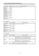
Note 1. Encoder pulse unit
2. This cannot be used in the torque control mode.
3. This cannot be used in the speed control mode.
4. For details on the value of the maximum current command (maximum torque) for 10 V ±4 V, refer to (d) in this section.
Summary of Contents for MR-J4W2-0303B6
Page 39: ...2 INSTALLATION 2 8 MEMO ...
Page 97: ...4 STARTUP 4 20 MEMO ...
Page 181: ...6 NORMAL GAIN ADJUSTMENT 6 28 MEMO ...
Page 235: ...9 DIMENSIONS 9 6 MEMO ...
Page 245: ...10 CHARACTERISTICS 10 10 MEMO ...
Page 309: ...13 USING STO FUNCTION 13 14 MEMO ...
Page 365: ...15 USING A DIRECT DRIVE MOTOR 15 24 MEMO ...
Page 389: ...16 FULLY CLOSED LOOP SYSTEM 16 24 MEMO ...
Page 461: ...17 APPLICATION OF FUNCTIONS 17 72 MEMO ...
Page 556: ...APPENDIX App 41 ...
Page 585: ...MEMO ...


