17. APPLICATION OF FUNCTIONS
17 - 24
No.
Symbol
Name and function
Initial
value
[unit]
Setting
range
Each/
common
PX30
DRT
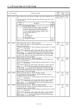
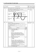
Drive recorder switching time setting
Set the drive recorder switching time.
When a USB communication is cut during using a graph function, the function will
be changed to the drive recorder function after the setting time of this parameter.
When a value from "1" to "32767" is set, it will switch after the setting value.
However, when "0" is set, it will switch after 600 s.
When "-1" is set, the drive recorder function is disabled.
0
[s]
-1
to
32767
Common
PX31
XOP4
Function selection X-4
Refer to Name and
function column.
Each
axis
Setting
digit
Explanation
Initial
value
_ _ _ x
Robust filter selection
0: Disabled
1: Enabled
When you select "Enabled" of this digit, the machine
resonance suppression filter 5 set in [Pr. PX22] is not
available.
0h
_ _ x _
For manufacturer setting
0h
_ x _ _
0h
x _ _ _
0h
PX43 **STOD STO
diagnosis
error detection time
Set the time from when an error occurs in the STO input signal or STO circuit until
the detection of [AL. 68.1 Mismatched STO signal error].
When 0 s is set, the detection of [AL. 68.1 Mismatched STO signal error] is not
performed.
The following shows safety levels at the time of parameter setting.
0
[s]
0 to
60
Common
Setting
value
STO input diagnosis
by TOFB output
Safety level
0
Execute
EN ISO 13849-1 Category 3 PL d, IEC
61508 SIL 2, and EN 62061 SIL CL2
Not
execute
1 to 60
Execute
EN ISO 13849-1 Category 3 PL e, IEC
61508 SIL 3, and EN 62061 SIL CL3
Not execute
EN ISO 13849-1 Category 3 PL d, IEC
61508 SIL 2, and EN 62061 SIL CL2
When the short-circuit connector is connected to the CN8 connector, set "0" in the
parameter.
This parameter is available with servo amplifiers with software version C1 or later.
Summary of Contents for MR-J4W2-0303B6
Page 39: ...2 INSTALLATION 2 8 MEMO ...
Page 97: ...4 STARTUP 4 20 MEMO ...
Page 181: ...6 NORMAL GAIN ADJUSTMENT 6 28 MEMO ...
Page 235: ...9 DIMENSIONS 9 6 MEMO ...
Page 245: ...10 CHARACTERISTICS 10 10 MEMO ...
Page 309: ...13 USING STO FUNCTION 13 14 MEMO ...
Page 365: ...15 USING A DIRECT DRIVE MOTOR 15 24 MEMO ...
Page 389: ...16 FULLY CLOSED LOOP SYSTEM 16 24 MEMO ...
Page 461: ...17 APPLICATION OF FUNCTIONS 17 72 MEMO ...
Page 556: ...APPENDIX App 41 ...
Page 585: ...MEMO ...

