17. APPLICATION OF FUNCTIONS
17 - 23
No.
Symbol
Name and function
Initial
value
[unit]
Setting
range
Each/
common
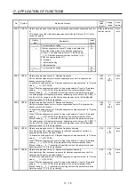
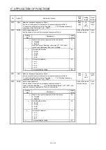
PX26 OSCL1 Vibration tough drive - Oscillation detection level
Set a filter readjustment sensitivity of [Pr. PB13 Machine resonance suppression
filter 1] and [Pr. PB15 Machine resonance suppression filter 2] while the vibration
tough drive is enabled.
However, setting "0" will be 50%.
Example: When you set "50" to the parameter, the filter will be readjusted at the
time of 50% or more oscillation level.
50
[%]
0
to
100
Each
axis
PX27 *OSCL2 Vibration tough drive function selection
Refer to Name and
function column.
Each
axis
Setting
digit
Explanation
Initial
value
_ _ _ x
Oscillation detection alarm selection
0: [AL. 54 Oscillation detection] will occur at oscillation
detection.
1: [AL. F3.1 Oscillation detection warning] will occur at
oscillation detection.
2: Oscillation detection function disabled
Select alarm or warning when an oscillation continues at
a filter readjustment sensitivity level of [Pr. PX26].
The digit is continuously enabled regardless of the
vibration tough drive in [Pr. PX25].
0h
_ _ x _
For manufacturer setting
0h
_ x _ _
0h
x _ _ _
0h
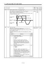
PX28
CVAT
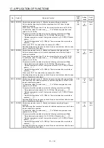
SEMI-F47 function - Instantaneous power failure detection time
Set the time until the occurrence of [AL. 10.1 Voltage drop in the control circuit
power].
This parameter setting range differs depending on the software version of the servo
amplifier as follows.
Software version C0 or later: Setting range 30 ms to 200 ms
Software version C1 or earlier: Setting range 30 ms to 500 ms
To comply with SEMI-F47 standard, it is unnecessary to change the initial value
(200 ms).
However, when the instantaneous power failure time exceeds 200 ms, and the
instantaneous power failure voltage is less than 70% of the rated input voltage, the
power may be normally turned off even if a value larger than 200 ms is set in the
parameter.
To disable the parameter, set "Disabled (_ 0 _ _)" of "SEMI-F47 function selection"
in [Pr. PX25].
200
[ms]
30
to
500
Common
PX29
DRAT
Drive recorder arbitrary alarm trigger setting
Refer to Name and
function column.
Common
Setting
digit
Explanation
Initial
value
_ _ x x
Alarm detail No. setting
Set the digits when you execute the trigger with arbitrary
alarm detail No. for the drive recorder function.
When these digits are "0 0", only the arbitrary alarm No.
setting will be enabled.
00h
x x _ _
Alarm No. setting
Set the digits when you execute the trigger with arbitrary
alarm No. for the drive recorder function.
When "0 0" are set, arbitrary alarm trigger of the drive
recorder will be disabled.
00h
Setting
example:
To activate the drive recorder when [AL. 50 Overload 1] occurs, set "5 0 0 0".
To activate the drive recorder when [AL. 50.3 Thermal overload error 4 during
operation] occurs, set "5 0 0 3".
Summary of Contents for MR-J4W2-0303B6
Page 39: ...2 INSTALLATION 2 8 MEMO ...
Page 97: ...4 STARTUP 4 20 MEMO ...
Page 181: ...6 NORMAL GAIN ADJUSTMENT 6 28 MEMO ...
Page 235: ...9 DIMENSIONS 9 6 MEMO ...
Page 245: ...10 CHARACTERISTICS 10 10 MEMO ...
Page 309: ...13 USING STO FUNCTION 13 14 MEMO ...
Page 365: ...15 USING A DIRECT DRIVE MOTOR 15 24 MEMO ...
Page 389: ...16 FULLY CLOSED LOOP SYSTEM 16 24 MEMO ...
Page 461: ...17 APPLICATION OF FUNCTIONS 17 72 MEMO ...
Page 556: ...APPENDIX App 41 ...
Page 585: ...MEMO ...

