


5. PARAMETERS
5 - 20
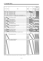
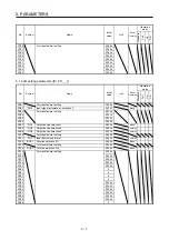
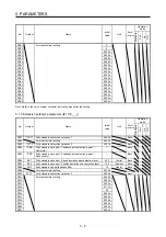
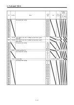
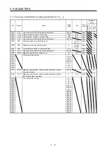
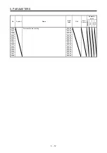
No.
Symbol
Name and function
Initial
value
[unit]
Setting
range
Each/
Common
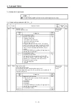
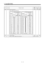
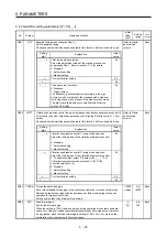
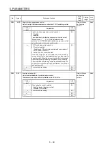
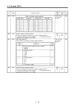
PA20
*TDS
Tough drive setting
Alarms may not be avoided with the tough drive function depending on the situations
of the power supply and load fluctuation.
You can assign MTTR (During tough drive) to pins CN3-11 to CN3-13, CN3-24, and
CN3-25 with [Pr. PD07] to [Pr. PD09]. For MR-J4W2-0303B6 servo amplifiers, MTTR
(during tough drive) cannot be assigned.
Refer to Name
and function
column.
Each
Setting
digit
Explanation
Initial
value
_ _ _ x
For manufacturer setting
0h
_ _ x _
Vibration tough drive selection
0: Disabled
1: Enabled
Selecting "1" enables to suppress vibrations by
automatically changing setting values of [Pr. PB13 Machine
resonance suppression filter 1] and [Pr. PB15 Machine
resonance suppression filter 2] in case that the vibration
exceed the value of the oscillation level set in [Pr. PF23].
Refer to section 7.3 for details.
0h
_ x _ _
SEMI-F47 function selection
0: Disabled
1: Enabled
Selecting "1" enables to avoid generating [AL. 10
Undervoltage] using the electrical energy charged in the
capacitor in case that an instantaneous power failure
occurs during operation. Set the time of until [AL. 10.1
Voltage drop in the control circuit power] occurs in [Pr.
PF25 SEMI-F47 function - Instantaneous power failure
detection time].
A specified axis cannot be enabled for the instantaneous
power failure tough drive function.
For MR-J4W2-0303B6 servo amplifiers, this digit cannot be
used other than the initial value.
0h
x _ _ _
For manufacturer setting
0h
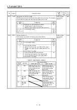
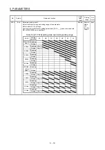
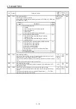
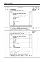
PA21
*AOP3 Function selection A-3
Refer to Name
and function
column.
Each
Setting
digit
Explanation
Initial
value
_ _ _ x
One-touch tuning function selection
0: Disabled
1: Enabled
When the digit is "0", the one-touch tuning with MR
Configurator2 will be disabled.
1h
_ _ x _
For manufacturer setting
0h
_ x _ _
0h
x _ _ _
0h
Summary of Contents for MR-J4W2-0303B6
Page 39: ...2 INSTALLATION 2 8 MEMO ...
Page 97: ...4 STARTUP 4 20 MEMO ...
Page 181: ...6 NORMAL GAIN ADJUSTMENT 6 28 MEMO ...
Page 235: ...9 DIMENSIONS 9 6 MEMO ...
Page 245: ...10 CHARACTERISTICS 10 10 MEMO ...
Page 309: ...13 USING STO FUNCTION 13 14 MEMO ...
Page 365: ...15 USING A DIRECT DRIVE MOTOR 15 24 MEMO ...
Page 389: ...16 FULLY CLOSED LOOP SYSTEM 16 24 MEMO ...
Page 461: ...17 APPLICATION OF FUNCTIONS 17 72 MEMO ...
Page 556: ...APPENDIX App 41 ...
Page 585: ...MEMO ...