11. OPTIONS AND PERIPHERAL EQUIPMENT
11 - 2
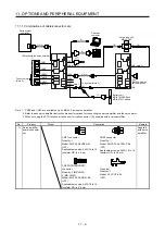
11.1.1 Combinations of cable/connector sets
Servo system
controller
Personal
computer
6) 7)
5)
2) 3) 4)
2) 3) 4)
Cap
(Packed with the
servo amplifier)
CN5
CN3
CN1B
CN2C (Note 1)
CN4
CN8 (Note 3)
CN1A
12)
11)
CN4
8)
9)
CNP1
CNP3B
CNP3C
(Note 1)
CNP3A
CN2B
CN2A
10)
10)
CN9
CN10
Safety logic unit
MR-J3-D05
To servo motor
(Note 2)
To encoder (Note 2)
CN8 (Note 3)
(Packed with the servo amplifier)
CNP2
CN1A
1)
Battery unit
MR-BT6VCASE and
MR-BAT6V1 battery
Note 1. CNP3 and CN2C are available only on MR-J4 3-axis servo amplifier.
2. Refer to each servo amplifier instruction manual for options for connecting the servo amplifier and the servo motor.
3. When not using the STO function, attach a short-circuit connector (13)) supplied with a servo amplifier.
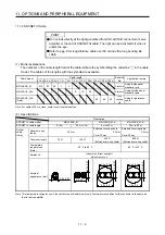
No. Product
Model
Description
Remark
1) Servo
amplifier
power connector
set
CNP1 connector
Quantity: 1
Model: 03JFAT-SAXGFK-43
(JST)
Applicable wire size: AWG 16 to 14
Insulator OD: to 4.2 mm
CNP2 connector
Quantity: 1
Model: 06JFAT-SAXYGG-F-KK
(JST)
Applicable wire size: AWG 16 to 14
Insulator OD: to 3.8 mm
Supplied
with servo
amplifier
CNP3A/CNP3B/CNP3C
connector
Quantity: 2 (MR-J4W2)
3 (MR-J4W3)
Model: 04JFAT-SAGG-G-KK
(JST)
Applicable wire size: AWG 18 to 14
Insulator OD: to 3.8 mm
Open tool
Quantity: 1
Model: J-FAT-OT-EXL
(JST)
Summary of Contents for MR-J4W2-0303B6
Page 39: ...2 INSTALLATION 2 8 MEMO ...
Page 97: ...4 STARTUP 4 20 MEMO ...
Page 181: ...6 NORMAL GAIN ADJUSTMENT 6 28 MEMO ...
Page 235: ...9 DIMENSIONS 9 6 MEMO ...
Page 245: ...10 CHARACTERISTICS 10 10 MEMO ...
Page 309: ...13 USING STO FUNCTION 13 14 MEMO ...
Page 365: ...15 USING A DIRECT DRIVE MOTOR 15 24 MEMO ...
Page 389: ...16 FULLY CLOSED LOOP SYSTEM 16 24 MEMO ...
Page 461: ...17 APPLICATION OF FUNCTIONS 17 72 MEMO ...
Page 556: ...APPENDIX App 41 ...
Page 585: ...MEMO ...

