6. NORMAL GAIN ADJUSTMENT
6 - 6
(2) Amplifier command method
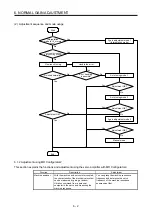
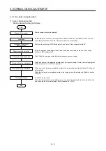
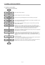
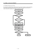
Make one-touch tuning as follows.
Start
Startup of the system
Movement to tuning start position
One-touch tuning start,
mode selection
Input of permissible
travel distance
Response mode selection
One-touch tuning execution
One-touch tuning completion
Tuning result check
One-touch tuning in progress
Controller reset
Servo amplifier power cycling
End
Start a system referring to chapter 4.
Move the moving part to the center of a movable range.
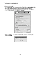
Start one-touch tuning of MR Configurator2, and select "Amplifier command method".
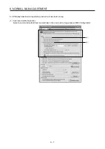
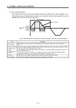
In the one-touch tuning window of MR Configurator2, input a maximum travel distance to move
the moving part at one-touch tuning.
Select a response mode (High mode, Basic mode, and Low mode) in the one-touch tuning
window of MR Configurator2.
While the servo motor is stopped, click "Start" to start one-touch tuning. After the tuning is
started, the servo motor will reciprocate automatically. Executing one-touch tuning during servo
motor rotation will cause an error. After one-touch tuning is executed using the amplifier
command method, control will not be performed by commands from the controller.
Gains and filters will be adjusted automatically. During processing of tuning, the tuning progress
will be displayed in % in MR Configurator2.
One-touch tuning will be completed automatically after the tuning. When one-touch tuning is
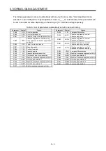
completed normally, the parameters described in table 6.1 will be updated automatically.
When the tuning is not completed normally, the tuning error will be displayed. (Refer to section
6.2.2 (5).)
Check the tuning result.
When the tuning result is not satisfactory, you can return the parameter to the value before the
one-touch tuning or the initial value. (Refer to section 6.2.2 (8).)
After executing the one-touch tuning, resetting the controller or cycling the power of the servo
amplifier returns to the state in which control is performed from the controller.
Summary of Contents for MR-J4W2-0303B6
Page 39: ...2 INSTALLATION 2 8 MEMO ...
Page 97: ...4 STARTUP 4 20 MEMO ...
Page 181: ...6 NORMAL GAIN ADJUSTMENT 6 28 MEMO ...
Page 235: ...9 DIMENSIONS 9 6 MEMO ...
Page 245: ...10 CHARACTERISTICS 10 10 MEMO ...
Page 309: ...13 USING STO FUNCTION 13 14 MEMO ...
Page 365: ...15 USING A DIRECT DRIVE MOTOR 15 24 MEMO ...
Page 389: ...16 FULLY CLOSED LOOP SYSTEM 16 24 MEMO ...
Page 461: ...17 APPLICATION OF FUNCTIONS 17 72 MEMO ...
Page 556: ...APPENDIX App 41 ...
Page 585: ...MEMO ...

