5. PARAMETERS
5 - 4
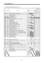
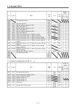
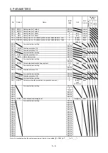
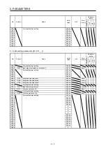
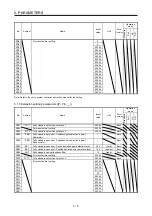
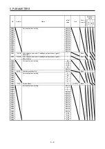
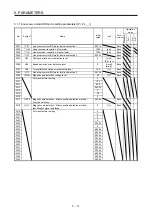
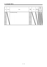
5.1.2 Gain/filter setting parameters ([Pr. PB_ _ ])
No. Symbol
Name
Initial
value
Unit
Each/
Common
Operation
mode
Standard
F
ull.
Lin.
D.D.
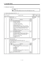
PB01
FILT
Adaptive tuning mode (adaptive filter II)
0000h
Each
PB02
VRFT
Vibration suppression control tuning mode (advanced vibration
suppression control II)
0000h Each
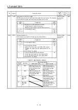
PB03 TFBGN Torque feedback loop gain
18000
[rad/s]
Each
PB04
FFC
Feed forward gain
0
[%]
Each
PB05
For manufacturer setting
500
PB06
GD2
Load to motor inertia ratio/load to motor mass ratio
7.00
[Multiplier]
Each
PB07
PG1
Model loop gain
15.0
[rad/s]
Each
PB08
PG2
Position loop gain
37.0
[rad/s]
Each
PB09
VG2
Speed loop gain
823
[rad/s]
Each
PB10
VIC
Speed integral compensation
33.7
[ms]
Each
PB11
VDC
Speed differential compensation
980
Each
PB12
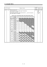
OVA
Overshoot amount compensation
0
[%]
Each
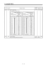
PB13
NH1
Machine resonance suppression filter 1
4500
[Hz]
Each
PB14
NHQ1
Notch shape selection 1
0000h
Each
PB15
NH2
Machine resonance suppression filter 2
4500
[Hz]
Each
PB16
NHQ2
Notch shape selection 2
0000h
Each
PB17
NHF
Shaft resonance suppression filter
0000h
Each
PB18
LPF
Low-pass filter setting
3141
[rad/s]
Each
PB19
VRF11 Vibration suppression control 1 - Vibration frequency
100.0
[Hz]
Each
PB20
VRF12 Vibration suppression control 1 - Resonance frequency
100.0
[Hz]
Each
PB21
VRF13 Vibration suppression control 1 - Vibration frequency damping
0.00
Each
PB22
VRF14 Vibration suppression control 1 - Resonance frequency damping
0.00
Each
PB23
VFBF
Low-pass filter selection
0000h
Each
PB24
*MVS
Slight vibration suppression control
0000h
Each
PB25
*BOP1 Function selection B-1
0000h
Each
PB26
*CDP
Gain switching function
0000h
Each
PB27
CDL
Gain switching condition
10
[kpulse/s]/
[pulse]/
[r/min]
Each
PB28
CDT
Gain switching time constant
1
[ms]
Each
PB29
GD2B
Load to motor inertia ratio/load to motor mass ratio after gain
switching
7.00 [Multiplier] Each
PB30
PG2B
Position loop gain after gain switching
0.0
[rad/s]
Each
PB31
VG2B
Speed loop gain after gain switching
0
[rad/s]
Each
PB32
VICB
Speed integral compensation after gain switching
0.0
[ms]
Each
PB33 VRF11B Vibration suppression control 1 - Vibration frequency after gain
switching
0.0 [Hz]
Each
PB34 VRF12B Vibration suppression control 1 - Resonance frequency after gain
switching
0.0 [Hz]
Each
PB35 VRF13B Vibration suppression control 1 - Vibration frequency damping
after gain switching
0.00 Each
PB36 VRF14B Vibration
suppression
control 1 - Resonance frequency damping
after gain switching
0.00 Each
PB37 For manufacturer setting
1600
PB38
0.00
PB39
0.00
PB40
0.00
PB41
0
PB42
0
Summary of Contents for MR-J4W2-0303B6
Page 39: ...2 INSTALLATION 2 8 MEMO ...
Page 97: ...4 STARTUP 4 20 MEMO ...
Page 181: ...6 NORMAL GAIN ADJUSTMENT 6 28 MEMO ...
Page 235: ...9 DIMENSIONS 9 6 MEMO ...
Page 245: ...10 CHARACTERISTICS 10 10 MEMO ...
Page 309: ...13 USING STO FUNCTION 13 14 MEMO ...
Page 365: ...15 USING A DIRECT DRIVE MOTOR 15 24 MEMO ...
Page 389: ...16 FULLY CLOSED LOOP SYSTEM 16 24 MEMO ...
Page 461: ...17 APPLICATION OF FUNCTIONS 17 72 MEMO ...
Page 556: ...APPENDIX App 41 ...
Page 585: ...MEMO ...


