APPENDIX
App. - 44
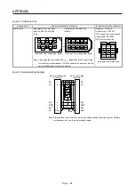
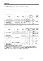
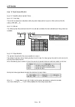
App. 8.2 Connector set
Connector set
1) Servo amplifier-side connector 2)
Servo
motor-side connector
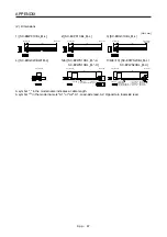
MR-ECNM Receptacle:
36210-0100PL
Shell kit: 36310-3200-008
(3M)
Connector set: 54599-1019
(Molex)
Housing: 1-172161-9
Connector pin: 170359-1
(TE Connectivity or equivalent)
Cable clamp: MTI-0002
(Toa Electric Industrial)
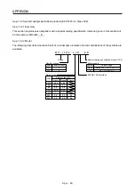
MR
1
2
3
MRR BAT
4
5
6
P5
7
8
9
LG SHD
View seen from wiring side.
CONT
MRR
LG
P5
MR
BAT
4
2
8
6
1
5
10
3
7
9
View seen from wiring side. (Note)
or
P5 MR
BAT
MRR
LG
1
3
7
9
4
2
8
6
10
5
View seen from wiring side. (Note)
Note. Keep open the pins shown with
. Especially, pin 10 is provided
for manufacturer adjustment. If it is connected with any other pin, the
servo amplifier cannot operate normally.
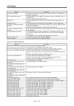
App. 8.3 Internal wiring diagram
(Note)
P5
LG
1
2
MR
MRR
3
4
3
7
9
SD
Plate
1
2
8
9
LG
MR
MRR
SHD
P5
BAT
BAT
Servo amplifier-side
connector
Servo motor-side
connector
Note. Always make connection for use in an absolute position detection system. Wiring is
not necessary for use in an incremental system.
Summary of Contents for MR-J4W2-0303B6
Page 39: ...2 INSTALLATION 2 8 MEMO ...
Page 97: ...4 STARTUP 4 20 MEMO ...
Page 181: ...6 NORMAL GAIN ADJUSTMENT 6 28 MEMO ...
Page 235: ...9 DIMENSIONS 9 6 MEMO ...
Page 245: ...10 CHARACTERISTICS 10 10 MEMO ...
Page 309: ...13 USING STO FUNCTION 13 14 MEMO ...
Page 365: ...15 USING A DIRECT DRIVE MOTOR 15 24 MEMO ...
Page 389: ...16 FULLY CLOSED LOOP SYSTEM 16 24 MEMO ...
Page 461: ...17 APPLICATION OF FUNCTIONS 17 72 MEMO ...
Page 556: ...APPENDIX App 41 ...
Page 585: ...MEMO ...


