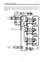
3. SIGNALS AND WIRING
3 - 7
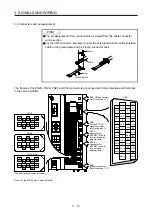
3.2.2 For source I/O interface
POINT
For notes, refer to section 3.2.1.
1
DI1-C
DI3-B
Plate SD
23
10
CN3
19
AND malfunction (Note 11)
(Note 2)
LBR-B
14
LG
11
CALM
12
25
MBR-B
13
MBR-C
3
LA-A
16
LAR-A
4
LB-A
17
LBR-A
5
LA-B
18
LAR-B
Servo amplifier
Electromagnetic brake
interlock A-axis
CN3
6
LB-B
Encoder A-phase pulse A-axis
Encoder B-phase pulse A-axis
Encoder A-phase pulse B-axis
Encoder B-phase pulse B-axis
(differential line driver) (Note 19)
(differential line driver) (Note 19)
(differential line driver) (Note 19)
Control common
(differential line driver) (Note 19)
(Note 13)
(Note 20)
(Note 3, 4) Forced stop 2
A-axis FLS
A-axis RLS
A-axis DOG
B-axis FLS
B-axis RLS
B-axis DOG
(Note 14)
DICOM
EM2
7
DI1-A
8
DI2-A
9
DI3-A
(Note 6)
SSCNET III cable
(option)
Servo system
controller
CN1A
CN1B
(Note 7)
(Note 1)
(Note 9)
Cap
(Note 5)
MR Configurator2
+
Personal
computer
CN5
USB cable
MR-J3USBCBL3M
(option)
20
DI1-B
21
DI2-B
22
Electromagnetic brake
interlock C-axis (Note 17)
MBR-A
RA1
RA2
RA3
RA4
(Note 10)
24 V DC
10 m or less
10 m or less
Electromagnetic brake
interlock B-axis
C-axis FLS
C-axis RLS
C-axis DOG
2
DI2-C
15
DI3-C
CN8
CN1A
CN1B
Servo amplifier
The last servo amplifier (Note 8)
CN1B
CN1A
(Note 18)
24
(Note 12)
(Note 6)
SSCNET III cable
(option)
(Note 7)
(Note 15)
Main circuit
power supply
(Note 16)
Short-circuit connector
(Packed with the servo amplifier)
(Note 10)
24 V DC
26
DOCOM
Summary of Contents for MR-J4W2-0303B6
Page 39: ...2 INSTALLATION 2 8 MEMO ...
Page 97: ...4 STARTUP 4 20 MEMO ...
Page 181: ...6 NORMAL GAIN ADJUSTMENT 6 28 MEMO ...
Page 235: ...9 DIMENSIONS 9 6 MEMO ...
Page 245: ...10 CHARACTERISTICS 10 10 MEMO ...
Page 309: ...13 USING STO FUNCTION 13 14 MEMO ...
Page 365: ...15 USING A DIRECT DRIVE MOTOR 15 24 MEMO ...
Page 389: ...16 FULLY CLOSED LOOP SYSTEM 16 24 MEMO ...
Page 461: ...17 APPLICATION OF FUNCTIONS 17 72 MEMO ...
Page 556: ...APPENDIX App 41 ...
Page 585: ...MEMO ...

