8. TROUBLESHOOTING
8 - 4
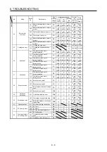
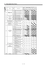
No. Name
Detail
No.
Detail name
Stop
method
(Note
2, 3)
Alarm deactivation
Process-
ing
system
(Note 8)
Stop
system
(Note 8)
Alarm
reset
CPU
reset
Cycling
the
power
Alarm
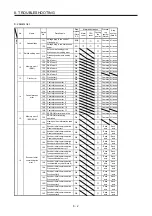
24
Main circuit error
24.1
Ground fault detected by
hardware detection circuit
DB
Each
axis
All axes
24.2
Ground fault detected by
software detection function
DB
Each
axis
All axes
25
Absolute position
erased
25.1
Servo motor encoder -
Absolute position erased
DB
Each
axis
Each
axis
25.2
Scale measurement encoder -
Absolute position erased
DB
Each
axis
Each
axis
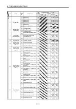
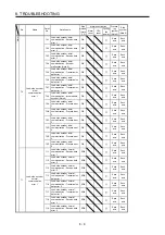
27.1
Initial magnetic pole detection -
Abnormal termination
DB
Each
axis
Each
axis
27.2
Initial magnetic pole detection -
Time out error
DB
Each
axis
Each
axis
27.3
Initial magnetic pole detection -
Limit switch error
DB
Each
axis
Each
axis
27
Initial magnetic
pole detection error
27.4
Initial magnetic pole detection -
Estimated error
DB
Each
axis
Each
axis
27.5
Initial magnetic pole detection -
Position deviation error
DB
Each
axis
Each
axis
27.6
Initial magnetic pole detection -
Speed deviation error
DB
Each
axis
Each
axis
27.7
Initial magnetic pole detection -
Current error
DB
Each
axis
Each
axis
28
Linear encoder
error 2
28.1
Linear encoder - Environment
error
EDB
Each
axis
Each
axis
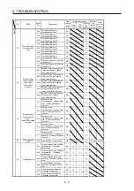
2A.1 Linear encoder error 1-1
EDB
Each
axis
Each
axis
2A.2 Linear encoder error 1-2
EDB
Each
axis
Each
axis
2A.3 Linear encoder error 1-3
EDB
Each
axis
Each
axis
2A
Linear encoder
error 1
2A.4 Linear encoder error 1-4
EDB
Each
axis
Each
axis
2A.5 Linear encoder error 1-5
EDB
Each
axis
Each
axis
2A.6 Linear encoder error 1-6
EDB
Each
axis
Each
axis
2A.7 Linear encoder error 1-7
EDB
Each
axis
Each
axis
2A.8 Linear encoder error 1-8
EDB
Each
axis
Each
axis
2B
Encoder counter
error
2B.1 Encoder counter error 1
EDB
Each
axis
Each
axis
2B.2 Encoder counter error 2
EDB
Each
axis
Each
axis
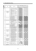
30.1 Regeneration heat error
DB
(Note 1)
(Note 1)
(Note 1)
Common All axes
30
Regenerative error 30.2 Regeneration signal error
DB
(Note 1)
(Note 1)
(Note 1)
Common All axes
30.3
Regeneration feedback signal
error
DB
(Note 1)
(Note 1)
(Note 1)
Common All axes
31
Overspeed
31.1 Abnormal motor speed
SD
Each
axis
Each
axis
32.1
Overcurrent detected at
hardware detection circuit
(during operation)
DB
Each
axis
All axes
32 Overcurrent
32.2
Overcurrent detected at
software detection function
(during operation)
DB
Each
axis
All axes
32.3
Overcurrent detected at
hardware detection circuit
(during a stop)
DB
Each
axis
All axes
32.4
Overcurrent detected at
software detection function
(during a stop)
DB
Each
axis
All axes
33
Overvoltage
33.1 Main circuit voltage error
EDB
Common All axes
Summary of Contents for MR-J4W2-0303B6
Page 39: ...2 INSTALLATION 2 8 MEMO ...
Page 97: ...4 STARTUP 4 20 MEMO ...
Page 181: ...6 NORMAL GAIN ADJUSTMENT 6 28 MEMO ...
Page 235: ...9 DIMENSIONS 9 6 MEMO ...
Page 245: ...10 CHARACTERISTICS 10 10 MEMO ...
Page 309: ...13 USING STO FUNCTION 13 14 MEMO ...
Page 365: ...15 USING A DIRECT DRIVE MOTOR 15 24 MEMO ...
Page 389: ...16 FULLY CLOSED LOOP SYSTEM 16 24 MEMO ...
Page 461: ...17 APPLICATION OF FUNCTIONS 17 72 MEMO ...
Page 556: ...APPENDIX App 41 ...
Page 585: ...MEMO ...

