5. PARAMETERS
5 - 7
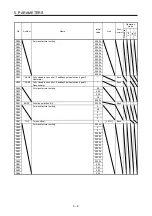
No. Symbol
Name
Initial
value
Unit
Each/
Common
Operation
mode
Standard
F
ull.
Lin.
D.D.
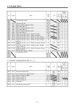
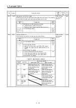
PC56 For manufacturer setting
0000h
PC57
0000h
PC58
0000h
PC59
0000h
PC60
0000h
PC61
0000h
PC62
0000h
PC63
0000h
PC64
0000h
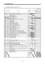
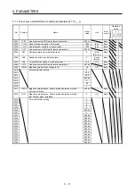
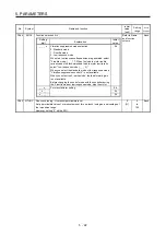
5.1.4 I/O setting parameters ([Pr. PD_ _ ])
No. Symbol
Name
Initial
value
Unit
Each/
Common
Operation
mode
Standard
F
ull.
Lin.
D.D.
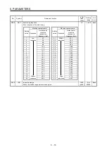
PD01
For manufacturer setting
0000h
PD02
*DIA2
Input signal automatic on selection 2
0000h
Each
PD03 For manufacturer setting
0020h
PD04
0021h
PD05
0022h
PD06
0000h
PD07
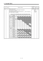
*DO1
Output device selection 1
0005h
Each
PD08
*DO2
Output device selection 2
0004h
Common
PD09
*DO3
Output device selection 3
0003h
Common
PD10
For manufacturer setting
0000h
PD11
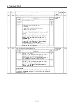
*DIF
Input filter setting (Note)
0004h
Common
PD12
*DOP1 Function selection D-1
0000h
Each
PD13
For manufacturer setting
0000h
PD14
*DOP3 Function selection D-3
0000h
Each
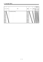
PD15 For manufacturer setting
0000h
PD16
0000h
PD17
0000h
PD18
0000h
PD19
0000h
PD20
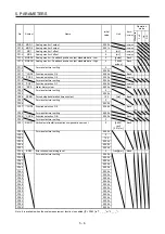
0
PD21
0
PD22
0
PD23
0
PD24
0000h
PD25
0000h
PD26
0000h
PD27
0000h
PD28
0000h
PD29
0000h
PD30
0
Summary of Contents for MR-J4W2-0303B6
Page 39: ...2 INSTALLATION 2 8 MEMO ...
Page 97: ...4 STARTUP 4 20 MEMO ...
Page 181: ...6 NORMAL GAIN ADJUSTMENT 6 28 MEMO ...
Page 235: ...9 DIMENSIONS 9 6 MEMO ...
Page 245: ...10 CHARACTERISTICS 10 10 MEMO ...
Page 309: ...13 USING STO FUNCTION 13 14 MEMO ...
Page 365: ...15 USING A DIRECT DRIVE MOTOR 15 24 MEMO ...
Page 389: ...16 FULLY CLOSED LOOP SYSTEM 16 24 MEMO ...
Page 461: ...17 APPLICATION OF FUNCTIONS 17 72 MEMO ...
Page 556: ...APPENDIX App 41 ...
Page 585: ...MEMO ...


