8. TROUBLESHOOTING
8 - 10
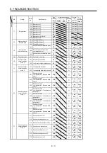
No. Name
Detail
No.
Detail name
Stop
method
(Note
2, 3)
Alarm deactivation
Process-
ing
system
(Note 8)
Stop
system
(Note 8)
Alarm
reset
CPU
reset
Cycling
the
power
Alarm
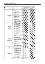
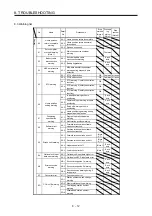
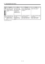
84
Network module
initialization error
84.1
Network module undetected
error
DB
84.2
Network module initialization
error 1
DB
84.3
Network module initialization
error 2
DB
85
Network module
error
85.1 Network module error 1
SD
85.2 Network module error 2
SD
85.3 Network module error 3
SD
86
Network
communication
error
86.1 Network communication error 1
SD
86.2 Network communication error 2
SD
86.3 Network communication error 3
SD
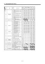
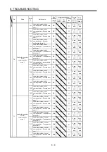
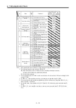
8A
USB communication
time-out error/
serial communication
time-out error/
Modbus RTU
communication
time-out error
8A.1
USB communication time-out
error/serial communication
time-out error
SD
Common All axes
8A.2
Modbus RTU communication
time-out error
SD
8D.1
CC-Link IE communication
error 1
SD
8D.2
CC-Link IE communication
error 2
SD
CC-Link IE
communication
error
8D.3 Master station setting error 1
DB
8D.5 Master station setting error 2
DB
8D
8D.6
CC-Link IE communication
error 3
SD
8D.7
CC-Link IE communication
error 4
SD
8D.8
CC-Link IE communication
error 5
SD
8D.9 Synchronization error 1
SD
8D.A Synchronization error 2
SD
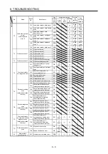
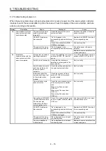
8E.1
USB communication receive
error/serial communication
receive error
SD
Common All axes
8E.2
USB communication checksum
error/serial communication
checksum error
SD
Common All axes
8E
USB communication
error/
serial communication
error/
Modbus RTU
communication error
8E.3
USB communication character
error/serial communication
character error
SD
Common All axes
8E.4
USB communication command
error/serial communication
command error
SD
Common All axes
8E.5
USB communication data
number error/serial
communication data number
error
SD
Common All axes
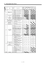
8E.6
Modbus RTU communication
receive error
SD
8E.7
Modbus RTU communication
message frame error
SD
8E.8
Modbus RTU communication
CRC error
SD
88888
Watchdog
8888._
Watchdog
DB
Common All axes
Summary of Contents for MR-J4W2-0303B6
Page 39: ...2 INSTALLATION 2 8 MEMO ...
Page 97: ...4 STARTUP 4 20 MEMO ...
Page 181: ...6 NORMAL GAIN ADJUSTMENT 6 28 MEMO ...
Page 235: ...9 DIMENSIONS 9 6 MEMO ...
Page 245: ...10 CHARACTERISTICS 10 10 MEMO ...
Page 309: ...13 USING STO FUNCTION 13 14 MEMO ...
Page 365: ...15 USING A DIRECT DRIVE MOTOR 15 24 MEMO ...
Page 389: ...16 FULLY CLOSED LOOP SYSTEM 16 24 MEMO ...
Page 461: ...17 APPLICATION OF FUNCTIONS 17 72 MEMO ...
Page 556: ...APPENDIX App 41 ...
Page 585: ...MEMO ...

