11. OPTIONS AND PERIPHERAL EQUIPMENT
11 - 16
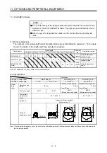
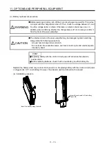
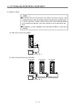
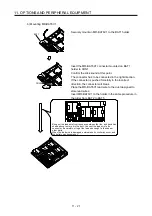
(b) Removal procedure
CAUTION
Pulling out the connector of the battery without the lock release lever pressed
may damage the CN4 connector of the servo amplifier or the connector of the
battery.
While pressing the lock release
lever, pull out the connector.
While pressing the lock release lever,
slide the battery case toward you.
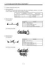
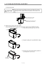
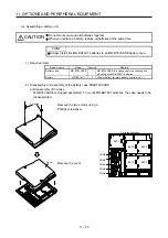
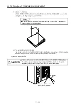
(4) Replacement procedure of the built-in battery
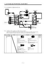
When the MR-BAT6V1SET-A reaches the end of its life, replace the built-in MR-BAT6V1 battery.
Tab
Cover
1) While pressing the locking part, open the cover.
2) Replace the battery with a new MR-BAT6V1 battery.
Projection
(four places)
3) Press the cover until it is fixed with the projection of
the locking part to close the cover.
Summary of Contents for MR-J4W2-0303B6
Page 39: ...2 INSTALLATION 2 8 MEMO ...
Page 97: ...4 STARTUP 4 20 MEMO ...
Page 181: ...6 NORMAL GAIN ADJUSTMENT 6 28 MEMO ...
Page 235: ...9 DIMENSIONS 9 6 MEMO ...
Page 245: ...10 CHARACTERISTICS 10 10 MEMO ...
Page 309: ...13 USING STO FUNCTION 13 14 MEMO ...
Page 365: ...15 USING A DIRECT DRIVE MOTOR 15 24 MEMO ...
Page 389: ...16 FULLY CLOSED LOOP SYSTEM 16 24 MEMO ...
Page 461: ...17 APPLICATION OF FUNCTIONS 17 72 MEMO ...
Page 556: ...APPENDIX App 41 ...
Page 585: ...MEMO ...

