5. PARAMETERS
5 - 55
No.
Symbol
Name and function
Initial
value
[unit]
Setting
range
Each/
Common
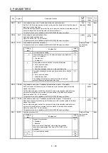
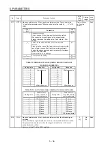
PL08
*LIT3
Linear servo motor/DD motor function selection 3
Refer to Name
and function
column.
Each
Setting
digit
Explanation
Initial
value
_ _ _ x
Magnetic pole detection method selection
0: Position detection method
4: Minute position detection method
0h
_ _ x _
For manufacturer setting
1h
_ x _ _
Magnetic pole detection - Stroke limit enabled/disabled
selection
0: Enabled
1: Disabled
0h
x _ _ _
For manufacturer setting
0h
PL09
LPWM Magnetic pole detection voltage level
Set a direct current exciting voltage level during the magnetic pole detection.
If [AL. 32 Overcurrent], [AL. 50 Overload 1], or [AL. 51 Overload 2] occurs during the
magnetic pole detection, decrease the setting value.
If [AL. 27 Initial magnetic pole detection error] occurs during the magnetic pole
detection, increase the setting value.
30
[%]
0 to
100
Each
Summary of Contents for MR-J4W2-0303B6
Page 39: ...2 INSTALLATION 2 8 MEMO ...
Page 97: ...4 STARTUP 4 20 MEMO ...
Page 181: ...6 NORMAL GAIN ADJUSTMENT 6 28 MEMO ...
Page 235: ...9 DIMENSIONS 9 6 MEMO ...
Page 245: ...10 CHARACTERISTICS 10 10 MEMO ...
Page 309: ...13 USING STO FUNCTION 13 14 MEMO ...
Page 365: ...15 USING A DIRECT DRIVE MOTOR 15 24 MEMO ...
Page 389: ...16 FULLY CLOSED LOOP SYSTEM 16 24 MEMO ...
Page 461: ...17 APPLICATION OF FUNCTIONS 17 72 MEMO ...
Page 556: ...APPENDIX App 41 ...
Page 585: ...MEMO ...


