17. APPLICATION OF FUNCTIONS
17 - 47
4) Vibration suppression control manual mode
POINT
When load-side vibration does not show up in servo motor-side vibration, the
setting of the servo motor-side vibration frequency does not produce an effect.
When the anti-resonance frequency and resonance frequency can be confirmed
using the machine analyzer or external equipment, do not set the same value
but set different values to improve the vibration suppression performance.
The setting range of [Pr. PB19], [Pr. PB20], [Pr. PX04], and [Pr. PX05] varies,
depending on the value in [Pr. PB07]. If a value out of the range is set, the
vibration suppression control will be disabled.
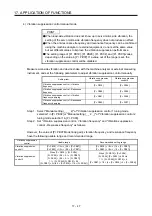
Measure work-side vibration and device shake with the machine analyzer or external measuring
instrument, and set the following parameters to adjust vibration suppression control manually.
Setting item
Vibration suppression
control 1
Vibration suppression
control 2
Vibration suppression control - Vibration
frequency
[Pr. PB19]
[Pr. PX04]
Vibration suppression control - Resonance
frequency
[Pr. PB20]
[Pr. PX05]
Vibration suppression control - Vibration
frequency damping
[Pr. PB21]
[Pr. PX06]
Vibration suppression control - Resonance
frequency damping
[Pr. PB22]
[Pr. PX07]
Step 1. Select "Manual setting (_ _ _ 2)" of "Vibration suppression control 1 tuning mode
selection" in [Pr. PB02] or "Manual setting (_ _ 2 _)" of "Vibration suppression control 2
tuning mode selection" in [Pr. PX03].
Step 2. Set "Vibration suppression control - Vibration frequency" and "Vibration suppression
control - Resonance frequency" as follows.
However, the value of [Pr. PB07 Model loop gain], vibration frequency, and resonance frequency
have the following usable range and recommended range.
Vibration suppression
control
Usable range
Recommended setting range
Vibration suppression
control 1
[Pr. PB19] > 1/2
π
× (0.9 × [Pr. PB07])
[Pr. PB20] > 1/2
π
× (0.9 × [Pr. PB07])
[Pr. PB19] > 1/2
π
× (1.5 × [Pr. PB07])
[Pr. PB20] > 1/2
π
× (1.5 × [Pr. PB07])
Vibration suppression
control 2
When [Pr. PB19] < [Pr. PX04],
[Pr. PX04] > (5.0 + 0.1 × [Pr. PB07])
[Pr. PX05] > (5.0 + 0.1 × [Pr. PB07])
1.1 < [Pr. PX04]/[Pr. PB19] < 5.5
[Pr. PB07] < 2
π
(0.3 × [Pr. PB19] + 1/8 × [Pr. PX04])
When [Pr. PB19] < [Pr. PX04],
[Pr. PX04], [Pr. PX05] > 6.25 Hz
1.1 < [Pr. PX04]/[Pr. PB19] < 4
[Pr. PB07] < 1/3 × (4 × [Pr. PB19] + 2 × [Pr. PX04])
Summary of Contents for MR-J4W2-0303B6
Page 39: ...2 INSTALLATION 2 8 MEMO ...
Page 97: ...4 STARTUP 4 20 MEMO ...
Page 181: ...6 NORMAL GAIN ADJUSTMENT 6 28 MEMO ...
Page 235: ...9 DIMENSIONS 9 6 MEMO ...
Page 245: ...10 CHARACTERISTICS 10 10 MEMO ...
Page 309: ...13 USING STO FUNCTION 13 14 MEMO ...
Page 365: ...15 USING A DIRECT DRIVE MOTOR 15 24 MEMO ...
Page 389: ...16 FULLY CLOSED LOOP SYSTEM 16 24 MEMO ...
Page 461: ...17 APPLICATION OF FUNCTIONS 17 72 MEMO ...
Page 556: ...APPENDIX App 41 ...
Page 585: ...MEMO ...


