17. APPLICATION OF FUNCTIONS
17 - 46
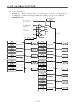
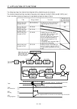
3) Vibration suppression control tuning procedure
The following flow chart is for the vibration suppression control 1. For the vibration suppression
control 2, set "_ _ 1 _" in [Pr. PX03] to execute the vibration suppression control tuning.
No
Vibration suppression control tuning
Operation
Is the target response
reached?
Execute or re-execute vibration
suppression control tuning.
(Set [Pr. PB02] to "_ _ _ 1".)
Decrease the response until vibration
of workpiece end/device is resolved.
End
Yes
No
No
Yes
Increase the response setting.
Has vibration of workpiece
end/device increased?
Has vibration
of workpiece end/device
been resolved?
Using a machine analyzer or
considering load-side vibration
waveform, set the vibration
suppression control manually.
Factor
Estimation cannot be made as load-side vibration
has not been transmitted to the servo motor side.
The response of the model loop gain has
increased to the load-side vibration frequency
(vibration suppression control limit).
Yes
Tuning ends automatically after
positioning operation is performed
the predetermined number of times.
([Pr. PB02] will be "_ _ _ 2" or
"_ _ _ 0".)
Stop operation.
Resume operation.
Summary of Contents for MR-J4W2-0303B6
Page 39: ...2 INSTALLATION 2 8 MEMO ...
Page 97: ...4 STARTUP 4 20 MEMO ...
Page 181: ...6 NORMAL GAIN ADJUSTMENT 6 28 MEMO ...
Page 235: ...9 DIMENSIONS 9 6 MEMO ...
Page 245: ...10 CHARACTERISTICS 10 10 MEMO ...
Page 309: ...13 USING STO FUNCTION 13 14 MEMO ...
Page 365: ...15 USING A DIRECT DRIVE MOTOR 15 24 MEMO ...
Page 389: ...16 FULLY CLOSED LOOP SYSTEM 16 24 MEMO ...
Page 461: ...17 APPLICATION OF FUNCTIONS 17 72 MEMO ...
Page 556: ...APPENDIX App 41 ...
Page 585: ...MEMO ...


