17. APPLICATION OF FUNCTIONS
17 - 58
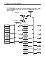
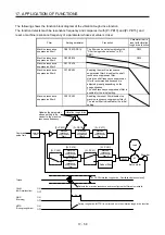
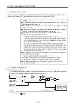
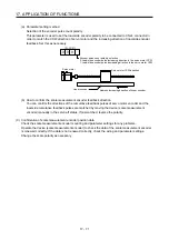
The following shows the function block diagram of the vibration tough drive function.
The function detects machine resonance frequency and compares it with [Pr. PB13] and [Pr. PB15], and
reset a machine resonance frequency of a parameter whose set value is closer.
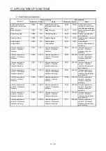
Filter Setting
parameter
Precaution
Parameter that is
reset with vibration
tough drive function
Machine resonance
suppression filter 1
PB01/PB13/PB14
The filter can be set automatically with
"Filter tuning mode selection" in [Pr.
PB01].
PB13
Machine resonance
suppression filter 2
PB15/PB16
PB15
Machine resonance
suppression filter 3
PX17/PX18
Machine resonance
suppression filter 4
PX19/PX20
Enabling the machine resonance
suppression filter 4 disables the shaft
resonance suppression filter.
Using the shaft resonance suppression
filter is recommended because it is
adjusted properly depending on the
usage situation.
The shaft resonance suppression filter is
enabled for the initial setting.
Machine resonance
suppression filter 5
PX21/PX22
Enabling the robust filter disables the
machine resonance suppression filter 5.
The robust filter is disabled for the initial
setting.
Command
pulse train
Command
filter
Encoder
Servo motor
PWM
M
Load
+
-
Machine
resonance
suppression
filter 1
[Pr. PB13]
[Pr. PB15]
[Pr. PX17]
Machine
resonance
suppression
filter 2
Machine
resonance
suppression
filter 3
Machine
resonance
suppression
filter 4
Machine
resonance
suppression
filter 5
Shaft
resonance
suppression
filter
Robust filter
[Pr. PX19]
[Pr. PX21]
[Pr. PB17]
[Pr. PX20]
[Pr. PX31]
Updates the parameter
whose setting is the
closest to the machine
resonance frequency.
Vibration tough drive
Torque
CALM
(AND malfunction)
WNG
(Warning)
MTTR
(During tough drive)
ON
OFF
[Pr. PX26 Vibration tough drive - Oscillation detection level]
Detects the machine resonance and reconfigures the filter automatically.
During tough drive (MTTR) is not turned on in the vibration tough drive function.
ON
OFF
ON
OFF
5 s
Summary of Contents for MR-J4W2-0303B6
Page 39: ...2 INSTALLATION 2 8 MEMO ...
Page 97: ...4 STARTUP 4 20 MEMO ...
Page 181: ...6 NORMAL GAIN ADJUSTMENT 6 28 MEMO ...
Page 235: ...9 DIMENSIONS 9 6 MEMO ...
Page 245: ...10 CHARACTERISTICS 10 10 MEMO ...
Page 309: ...13 USING STO FUNCTION 13 14 MEMO ...
Page 365: ...15 USING A DIRECT DRIVE MOTOR 15 24 MEMO ...
Page 389: ...16 FULLY CLOSED LOOP SYSTEM 16 24 MEMO ...
Page 461: ...17 APPLICATION OF FUNCTIONS 17 72 MEMO ...
Page 556: ...APPENDIX App 41 ...
Page 585: ...MEMO ...


