11. OPTIONS AND PERIPHERAL EQUIPMENT
11 - 32
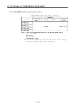
(1) For MR-J4W2
Total output of rotary servo
motors
Total continuous thrust of linear
servo motors
Total output of direct drive
motors
Power factor improving AC
reactor
450 W or less
150 N or less
100 W or less
FR-HAL-0.75K
From over 450 W to 600 W
From over 150 N to 240 N
From over 100 W to 377 W
FR-HAL-1.5K
From over 600 W to 1 kW
From over 240 N to 300 N
From over 377 W to 545 W
FR-HAL-2.2K
From over 1 kW to 20 kW
From over 300 N to 720 N
From over 545 W to 838 W
FR-HAL-3.7K
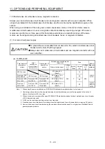
(2) For MR-J4W3
Total output of rotary servo
motors
Total continuous thrust of linear
servo motors
Total output of direct drive
motors
Power factor improving AC
reactor
450 W or less
150 N or less
FR-HAL-0.75K
From over 450 W to 600 W
From over 150 N to 240 N
378 W or less
FR-HAL-1.5K
From over 600 W to 1 kW
From over 240 N to 300 N
FR-HAL-2.2K
From over 1 kW to 20 kW
From over 300 N to 450 N
FR-HAL-3.7K
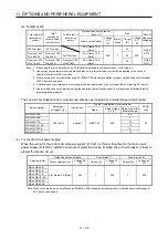
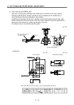
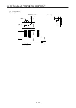
(3) Dimensions
Power factor
improving AC
reactor
Dimensions [mm]
Terminal
size
Mass
[kg]
W W1
H
D
(Note 1)
D1 D2 d
FR-HAL-0.75K 104 84
99 74 56
44
M5 M4 0.8
FR-HAL-1.5K 104 84
99
77
61
50
M5 M4 1.1
FR-HAL-2.2K
115
(Note 1)
40 115 77 71 57 M6 M4
1.5
FR-HAL-3.7K
115
(Note 1)
40 115 83 81 67 M6 M4
2.2
Note 1. Maximum dimension. The dimension varies depending on the input/output lines.
2. Selection conditions of wire size are as follows.
600 V grade heat-resistant polyvinyl chloride insulated wire (HIV wire)
Construction condition: One wire is constructed in the air
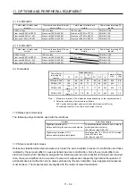
11.8 Relays (recommended)
The following relays should be used with the interfaces
Interface Selection
example
Digital input interface DI-1
Relay used for digital input command signals
To prevent defective contacts , use a relay for
small signal (twin contacts).
(Ex.) Omron : type G2A , MY
Digital output (interface DO-1)
Relay used for digital output signals
Small relay with 12 V DC or 24 V DC of rated
current 40 mA or less
(Ex.) Omron : type MY
11.9 Noise reduction techniques
Noises are classified into external noises which enter the servo amplifier to cause it to malfunction and those
radiated by the servo amplifier to cause peripheral devices to malfunction. Since the servo amplifier is an
electronic device which handles small signals, the following general noise reduction techniques are required.
Also, the servo amplifier can be a source of noise as its outputs are chopped by high carrier frequencies. If
peripheral devices malfunction due to noises produced by the servo amplifier, noise suppression measures
must be taken. The measures will vary slightly with the routes of noise transmission.
Summary of Contents for MR-J4W2-0303B6
Page 39: ...2 INSTALLATION 2 8 MEMO ...
Page 97: ...4 STARTUP 4 20 MEMO ...
Page 181: ...6 NORMAL GAIN ADJUSTMENT 6 28 MEMO ...
Page 235: ...9 DIMENSIONS 9 6 MEMO ...
Page 245: ...10 CHARACTERISTICS 10 10 MEMO ...
Page 309: ...13 USING STO FUNCTION 13 14 MEMO ...
Page 365: ...15 USING A DIRECT DRIVE MOTOR 15 24 MEMO ...
Page 389: ...16 FULLY CLOSED LOOP SYSTEM 16 24 MEMO ...
Page 461: ...17 APPLICATION OF FUNCTIONS 17 72 MEMO ...
Page 556: ...APPENDIX App 41 ...
Page 585: ...MEMO ...

