5. PARAMETERS
5 - 14
No.
Symbol
Name and function
Initial
value
[unit]
Setting
range
Each/
Common
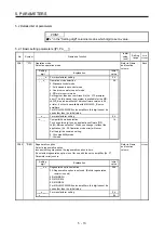
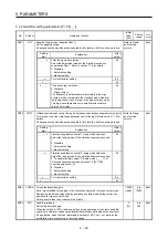
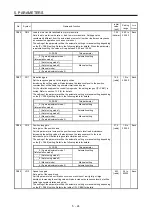
PA03
*ABS
Absolute position detection system
Set this parameter when using the absolute position detection system. The parameter
is not available in the speed control mode and torque control mode.
Refer to Name
and function
column.
Each
Setting
digit
Explanation
Initial
value
_ _ _ x
Absolute position detection system selection
0: Disabled (used in incremental system)
1: Enabled (used in absolute position detection system)
0h
_ _ x _
For manufacturer setting
0h
_ x _ _
0h
x _ _ _
0h
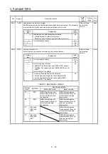
PA04
*AOP1 Function selection A-1
Select a forced stop input and forced stop deceleration function.
Refer to Name
and function
column.
Common
Setting
digit
Explanation
Initial
value
_ _ _ x
For manufacturer setting
0h
_ _ x _
0h
_ x _ _
Servo forced stop selection
0: Enabled (The forced stop input EM2 or EM1 is used.)
1: Disabled (The forced stop input EM2 and EM1 are not
used.)
Refer to table 5.1 for details.
0h
x _ _ _
Forced stop deceleration function selection
0: Forced stop deceleration function disabled (EM1)
2: Forced stop deceleration function enabled (EM2)
Refer to table 5.1 for details.
2h
Table 5.1 Deceleration method
Setting
value
EM2/EM1
Deceleration method
EM2 or EM1 is off
Alarm occurred
0 0 _ _
EM1
MBR (Electromagnetic
brake interlock) turns off
without the forced stop
deceleration.
MBR (Electromagnetic
brake interlock) turns off
without the forced stop
deceleration.
2 0 _ _
EM2
MBR (Electromagnetic
brake interlock) turns off
after the forced stop
deceleration.
MBR (Electromagnetic
brake interlock) turns off
after the forced stop
deceleration.
0 1 _ _ Not using
EM2 and
EM1
MBR
(Electromagnetic
brake interlock) turns off
without the forced stop
deceleration.
2 1 _ _ Not using
EM2 and
EM1
MBR
(Electromagnetic
brake interlock) turns off
after the forced stop
deceleration.
Summary of Contents for MR-J4W2-0303B6
Page 39: ...2 INSTALLATION 2 8 MEMO ...
Page 97: ...4 STARTUP 4 20 MEMO ...
Page 181: ...6 NORMAL GAIN ADJUSTMENT 6 28 MEMO ...
Page 235: ...9 DIMENSIONS 9 6 MEMO ...
Page 245: ...10 CHARACTERISTICS 10 10 MEMO ...
Page 309: ...13 USING STO FUNCTION 13 14 MEMO ...
Page 365: ...15 USING A DIRECT DRIVE MOTOR 15 24 MEMO ...
Page 389: ...16 FULLY CLOSED LOOP SYSTEM 16 24 MEMO ...
Page 461: ...17 APPLICATION OF FUNCTIONS 17 72 MEMO ...
Page 556: ...APPENDIX App 41 ...
Page 585: ...MEMO ...


