4
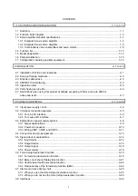
11. OPTIONS AND PERIPHERAL EQUIPMENT
11- 1 to 11-46
11.1 Cable/connector sets .................................................................................................................... 11- 1
11.1.1 Combinations of cable/connector sets ................................................................................... 11- 2
11.1.2 SSCNET III cable ................................................................................................................... 11- 4
11.1.3 Battery cable/junction battery cable ....................................................................................... 11- 6
11.1.4 MR-D05UDL3M-B STO cable ................................................................................................ 11- 7
11.2 Regenerative options .................................................................................................................... 11- 7
11.2.1 Combination and regenerative power .................................................................................... 11- 7
11.2.2 Selection of regenerative option ............................................................................................ 11- 8
11.2.3 Parameter setting .................................................................................................................. 11-10
11.2.4 Connection of regenerative option ........................................................................................ 11-11
11.2.5 Dimensions ........................................................................................................................... 11-12
11.3 Battery .......................................................................................................................................... 11-13
11.3.1 Selection of battery ............................................................................................................... 11-13
11.3.2 MR-BAT6V1SET-A battery ................................................................................................... 11-14
11.3.3 MR-BT6VCASE battery case ................................................................................................ 11-17
11.3.4 MR-BAT6V1 battery .............................................................................................................. 11-23
11.4 MR Configurator2 ........................................................................................................................ 11-24
11.4.1 Specifications ........................................................................................................................ 11-24
11.4.2 System configuration
............................................................................................................. 11-25
11.4.3 Precautions for using USB communication function ............................................................. 11-26
11.5 Selection example of wires .......................................................................................................... 11-27
11.6 Molded-case circuit breakers, fuses, magnetic contactors ......................................................... 11-29
11.7 Power factor improving AC reactors ............................................................................................ 11-31
11.8 Relays (recommended) ............................................................................................................... 11-32
11.9 Noise reduction techniques ......................................................................................................... 11-32
11.10 Earth-leakage current breaker ................................................................................................... 11-39
11.11 EMC filter (recommended) ........................................................................................................ 11-42
11.12 Junction terminal block MR-TB26A ........................................................................................... 11-45
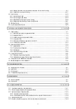
12. ABSOLUTE POSITION DETECTION SYSTEM
12- 1 to 12- 4
12.1 Summary
....................................................................................................................................... 12- 1
12.1.1 Features ................................................................................................................................. 12- 1
12.1.2 Structure ................................................................................................................................. 12- 1
12.1.3 Parameter setting ................................................................................................................... 12- 1
12.1.4 Confirmation of absolute position detection data ................................................................... 12- 2
12.2 Battery ........................................................................................................................................... 12- 3
12.2.1 Using MR-BAT6V1SET battery (only for MR-J4W2-0303B6) ............................................... 12- 3
12.2.2 Using MR-BT6VCASE battery case ....................................................................................... 12- 4
13. USING STO FUNCTION
13- 1 to 13-14
13.1 Introduction ................................................................................................................................... 13- 1
13.1.1 Summary ................................................................................................................................ 13- 1
13.1.2 Terms related to safety .......................................................................................................... 13- 1
13.1.3 Cautions ................................................................................................................................. 13- 1
13.1.4 Residual risks of the STO function ......................................................................................... 13- 2
13.1.5 Specifications ......................................................................................................................... 13- 3
13.1.6 Maintenance ........................................................................................................................... 13- 4
Summary of Contents for MR-J4W2-0303B6
Page 39: ...2 INSTALLATION 2 8 MEMO ...
Page 97: ...4 STARTUP 4 20 MEMO ...
Page 181: ...6 NORMAL GAIN ADJUSTMENT 6 28 MEMO ...
Page 235: ...9 DIMENSIONS 9 6 MEMO ...
Page 245: ...10 CHARACTERISTICS 10 10 MEMO ...
Page 309: ...13 USING STO FUNCTION 13 14 MEMO ...
Page 365: ...15 USING A DIRECT DRIVE MOTOR 15 24 MEMO ...
Page 389: ...16 FULLY CLOSED LOOP SYSTEM 16 24 MEMO ...
Page 461: ...17 APPLICATION OF FUNCTIONS 17 72 MEMO ...
Page 556: ...APPENDIX App 41 ...
Page 585: ...MEMO ...


