14. USING A LINEAR SERVO MOTOR
14 - 6
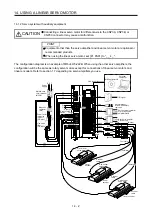
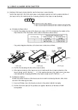
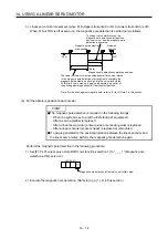
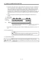
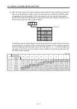
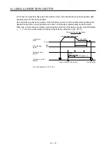
(3) Settings of the linear encoder direction and the linear servo motor direction
Set the first digit of [Pr. PC27] (Encoder pulse count polarity selection) so that the positive direction of
the linear servo motor matches with the increasing direction of the linear encoder feedback.
[Pr. PC27]
Encoder pulse count polarity selection
0: Linear servo motor positive direction and linear encoder increasing direction
1: Linear servo motor positive direction and linear encoder decreasing direction
(a) Parameter setting method
1) Confirm the positive direction of the linear servo motor. [Pr. PA14] determines the relation of the
travel direction of the linear servo motor under commands as shown below.
[Pr. PA14] setting
Travel direction of linear servo motor
Address increasing
command
Address decreasing
command
0
Positive direction
Negative direction
1
Negative direction
Positive direction
The positive/negative directions of the linear servo motor are as follows.
Secondary
side
Primary side
Positive
direction
Negative
direction
LM-H3 series
Negative direction
Positive
direction
Secondary side
Primary
side
LM-U2 series
Negative
direction
Positive
direction
Table
Primary
side
Secondary
side
LM-K2 series
2) Confirm the increasing direction of the linear encoder.
3) If the positive direction of the linear servo motor matches with the increasing direction of the
linear encoder, set [Pr. PC27] to "_ _ _ 0". If the positive direction of the linear servo motor does
not match with the increasing direction of the linear encoder, set [Pr. PC27] to "_ _ _ 1".
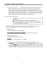
(b) Confirmation method
Confirm the positive direction of the linear servo motor and the increasing direction of the linear
encoder in the following procedure.
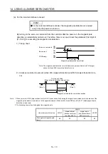
1) In servo-off status, move the linear servo motor in the positive direction manually.
2) Confirm the motor speed (in the positive and negative directions) at that time with MR
Configurator2.
Summary of Contents for MR-J4W2-0303B6
Page 39: ...2 INSTALLATION 2 8 MEMO ...
Page 97: ...4 STARTUP 4 20 MEMO ...
Page 181: ...6 NORMAL GAIN ADJUSTMENT 6 28 MEMO ...
Page 235: ...9 DIMENSIONS 9 6 MEMO ...
Page 245: ...10 CHARACTERISTICS 10 10 MEMO ...
Page 309: ...13 USING STO FUNCTION 13 14 MEMO ...
Page 365: ...15 USING A DIRECT DRIVE MOTOR 15 24 MEMO ...
Page 389: ...16 FULLY CLOSED LOOP SYSTEM 16 24 MEMO ...
Page 461: ...17 APPLICATION OF FUNCTIONS 17 72 MEMO ...
Page 556: ...APPENDIX App 41 ...
Page 585: ...MEMO ...


