13. USING STO FUNCTION
13 - 8
Note 1. Set the delay time of STO output with SW1 and SW2. These switches are located where dented from the front panel.
2. To release the STO state (base circuit shut-off), turn RESA and RESB on and turn them off.
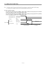
(2) Basic operation example
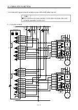
The switch status of STOA is input to SDI2A+ of MR-J3-D05, and then it will be input to STO1 and STO2
of the servo amplifier via SDO1A and SDO2A of MR-J3-D05.
The switch status of STOB is input to SDI2B+ of MR-J3-D05, and then it will be input to STO1 and STO2
of the servo amplifier via SDO1B and SDO2B of MR-J3-D05.
A-axis shutdown 1 and 2
B-axis shutdown 1 and 2
STO1, STO2
Stop
Operation
Energizing (close)
Shut-off (open)
EM2 input
STO shut-off
Normal (close)
Shut-off (open)
0 r/min
Servo motor drivable
Servo motor speed
Servo amplifier
Shut off delay
STO status
Summary of Contents for MR-J4W2-0303B6
Page 39: ...2 INSTALLATION 2 8 MEMO ...
Page 97: ...4 STARTUP 4 20 MEMO ...
Page 181: ...6 NORMAL GAIN ADJUSTMENT 6 28 MEMO ...
Page 235: ...9 DIMENSIONS 9 6 MEMO ...
Page 245: ...10 CHARACTERISTICS 10 10 MEMO ...
Page 309: ...13 USING STO FUNCTION 13 14 MEMO ...
Page 365: ...15 USING A DIRECT DRIVE MOTOR 15 24 MEMO ...
Page 389: ...16 FULLY CLOSED LOOP SYSTEM 16 24 MEMO ...
Page 461: ...17 APPLICATION OF FUNCTIONS 17 72 MEMO ...
Page 556: ...APPENDIX App 41 ...
Page 585: ...MEMO ...

