18. MR-J4W2-0303B6 SERVO AMPLIFIER
18 - 28
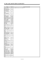
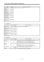
Device
Symbol
Function and application
AND electromagnetic
brake interlock
CMBR
For details of device, refer to section 3.5.2.
OR electromagnetic
brake interlock
XMBR
Electromagnetic
brake interlock for A-
axis
MBR-A
Electromagnetic
brake interlock for B-
axis
MBR-B
AND malfunction
CALM
OR malfunction
XALM
Malfunction for A-axis
ALM-A
Malfunction for B-axis
ALM-B
AND in-position
CINP
OR in-position
XINP
In-position for A-axis
INP-A
In-position for B-axis
INP-B
AND ready
CRD
OR ready
XRD
Common ready for A-
axis
RD-A
Common ready for B-
axis
RD-B
AND speed reached
CSA
OR speed reached
XSA
Speed reached for A-
axis
SA-A
Speed reached for B-
axis
SA-B
AND limiting speed
CVLC
OR limiting speed
XVLC
Limiting speed for A-
axis
VLC-A
Limiting speed for B-
axis
VLC-B
AND zero speed
detection
CZSP
OR zero speed
detection
XZSP
Zero speed detection
for A-axis
ZSP-A
Zero speed detection
for B-axis
ZSP-B
AND limiting torque
CTLC
OR limiting torque
XTLC
Limiting torque for A-
axis
TLC-A
Limiting torque for B-
axis
TLC-B
AND warning
CWNG
OR warning
XWNG
Warning for A-axis
WNG-A
Warning for B-axis
WNG-B
AND battery warning
CBWNG
OR battery warning
XBWNG
Battery warning for A-
axis
BWNG-A
Battery warning for B-
axis
BWNG-B
Summary of Contents for MR-J4W2-0303B6
Page 39: ...2 INSTALLATION 2 8 MEMO ...
Page 97: ...4 STARTUP 4 20 MEMO ...
Page 181: ...6 NORMAL GAIN ADJUSTMENT 6 28 MEMO ...
Page 235: ...9 DIMENSIONS 9 6 MEMO ...
Page 245: ...10 CHARACTERISTICS 10 10 MEMO ...
Page 309: ...13 USING STO FUNCTION 13 14 MEMO ...
Page 365: ...15 USING A DIRECT DRIVE MOTOR 15 24 MEMO ...
Page 389: ...16 FULLY CLOSED LOOP SYSTEM 16 24 MEMO ...
Page 461: ...17 APPLICATION OF FUNCTIONS 17 72 MEMO ...
Page 556: ...APPENDIX App 41 ...
Page 585: ...MEMO ...


