


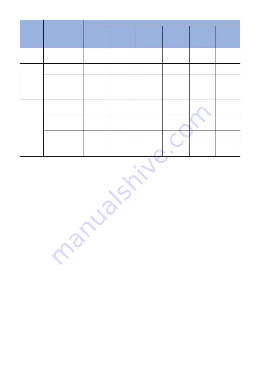
Control
timing
Conditions for exe-
cution
Type of control
Laser power
correction
control
D-half con-
trol
ARCDAT
control
Color dis-
placement
correction
control
Patch Sen-
sor adjust-
ment
PASCAL
control
At job com-
pletion
At last rotation for each
accumulated 1000 im-
ages
Yes
Yes
Yes
-
Yes
-
At parts re-
placement
When replacing the
Drum Unit
Yes
Yes
Yes
Yes
Yes
-
When replacing the De-
veloping Unit (when IN-
ISET-Y/M/C/K/4C is
executed in service
mode)
Yes
Yes
Yes
-
Yes
-
When the
Settings/
Registration
menu is exe-
cuted
When Auto Gradation
Adjustment > Full Ad-
just is executed
Yes
Yes
Yes
-
Yes
Yes
When Auto Gradation
Adjustment > Quick Ad-
just is executed
Yes
Yes
Yes
-
Yes
-
When Correct Shading
is executed
Yes
Yes
Yes
-
-
-
When Auto Correct
Color Mismatch is exe-
cuted
-
-
-
Yes
-
-
● Laser Power Correction (D-max) Control
Purpose
To determine the optimal laser output
Control description
1. The Main Controller PCB forms the patch pattern of the target color on the ITB.
2. The DC Controller measures the patch density using the Registration Patch Sensor Unit (Rear/Front) (UN25/26) and
corrects the laser output for each color to get the target density.
● D-half Control
Purpose
Top determine the optimal image gradation
Control description
1. The Main Controller PCB outputs patch data in each color (Y/M/C/Bk) to the DC Controller PCB.
2. The DC Controller PCB forms a patch pattern of each color (Y/M/C/Bk) on the ITB from this data.
3. The DC Controller measures the patch pattern using the Registration Patch Sensor Unit (Rear/Front) (UN25/26) and
the result is sent to the Main Controller PCB.
4. Based on the data above, the Main Controller PCB executes gradation correction to obtain ideal halftone image.
● ARCDAT Control (Automatic and Reciprocal Color Density Adjustment Technology)
Purpose
To realize the ideal gradation characteristics while reducing downtime
Control description
1. The Main Controller PCB outputs patch data in each color (Y/M/C/Bk) to the DC Controller PCB.
2. The DC Controller PCB forms a patch pattern of each color (Y/M/C/Bk) on the ITB.
2. Technology
79
Summary of Contents for imageRUNNER ADVANCE C3330 Series
Page 1: ...Revision 7 0 imageRUNNER ADVANCE C3330 C3325 C3320 Series Service Manual ...
Page 18: ...Product Overview 1 Product Lineup 7 Features 11 Specifications 17 Parts Name 26 ...
Page 518: ...Error Jam Alarm 7 Overview 507 Error Code 511 Jam Code 617 Alarm Code 624 ...
Page 1020: ...9 Installation 1008 ...
Page 1022: ...2 Perform steps 3 to 5 in each cassette 9 Installation 1010 ...
Page 1024: ...5 6 Checking the Contents Cassette Feeding Unit 1x 3x 2x 1x 9 Installation 1012 ...
Page 1027: ...3 4 NOTE The removed cover will be used in step 6 5 2x 2x 9 Installation 1015 ...
Page 1046: ...When the Kit Is Not Used 1 2 Close the Cassette 2 When the Kit Is Used 1 9 Installation 1034 ...
Page 1068: ... Removing the Covers 1 2x 2 1x 9 Installation 1056 ...
Page 1070: ...3 1x 1x 9 Installation 1058 ...
Page 1083: ...6 7 TP M4x8 2x 2x 9 Installation 1071 ...
Page 1084: ...When Installing the USB Keyboard 1 Cap Cover Wire Saddle 9 Installation 1072 ...
Page 1129: ...9 2x 10 2x 11 9 Installation 1117 ...
Page 1135: ...Remove the covers 1 ws 2x 2 1x 9 Installation 1123 ...
Page 1140: ...2 2x 3 Connect the power plug to the outlet 4 Turn ON the power switch 9 Installation 1128 ...
Page 1176: ... A 2x Installing the Covers 1 1x 2 2x 9 Installation 1164 ...
Page 1190: ...14 Install the Cable Guide to the HDD Frame 4 Hooks 1 Boss 9 Installation 1178 ...


