


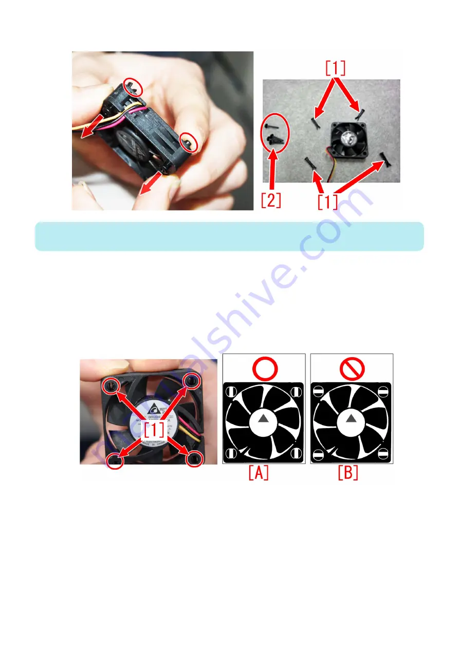
4. Push the 4 Fixation Pins [1] from the back side of the fan to remove them.
NOTE:
The 4 Fixation Pins [1] and the pins [2] removed in step 2 will be reused later, so do not dispose of them.
● Installation Procedure
1. After replacing the fan with a new one and inserting the 4 Fixation Pins removed in step 4 of "Removal Procedure",
install the fan to the heat sink.
When inserting the Fixation Pins to the fan, pay attention to the orientation of the pins so that the ends of the pins open to
the right and left as shown in the picture [1] and figure [A] below. If the pins are inserted such that the ends of the pins open
upward and downward as shown in figure [B], the ends of the pins will not open sufficiently when installing the fan onto the
heat sink, and the fan will not be installed properly. Pushing the fan hard in this configuration may cause the heat sink to
become loose.
2. Insert the 4 pins removed in step 2.
4. Parts Replacement and Cleaning
312
Summary of Contents for imageRUNNER ADVANCE C3330 Series
Page 1: ...Revision 7 0 imageRUNNER ADVANCE C3330 C3325 C3320 Series Service Manual ...
Page 18: ...Product Overview 1 Product Lineup 7 Features 11 Specifications 17 Parts Name 26 ...
Page 518: ...Error Jam Alarm 7 Overview 507 Error Code 511 Jam Code 617 Alarm Code 624 ...
Page 1020: ...9 Installation 1008 ...
Page 1022: ...2 Perform steps 3 to 5 in each cassette 9 Installation 1010 ...
Page 1024: ...5 6 Checking the Contents Cassette Feeding Unit 1x 3x 2x 1x 9 Installation 1012 ...
Page 1027: ...3 4 NOTE The removed cover will be used in step 6 5 2x 2x 9 Installation 1015 ...
Page 1046: ...When the Kit Is Not Used 1 2 Close the Cassette 2 When the Kit Is Used 1 9 Installation 1034 ...
Page 1068: ... Removing the Covers 1 2x 2 1x 9 Installation 1056 ...
Page 1070: ...3 1x 1x 9 Installation 1058 ...
Page 1083: ...6 7 TP M4x8 2x 2x 9 Installation 1071 ...
Page 1084: ...When Installing the USB Keyboard 1 Cap Cover Wire Saddle 9 Installation 1072 ...
Page 1129: ...9 2x 10 2x 11 9 Installation 1117 ...
Page 1135: ...Remove the covers 1 ws 2x 2 1x 9 Installation 1123 ...
Page 1140: ...2 2x 3 Connect the power plug to the outlet 4 Turn ON the power switch 9 Installation 1128 ...
Page 1176: ... A 2x Installing the Covers 1 1x 2 2x 9 Installation 1164 ...
Page 1190: ...14 Install the Cable Guide to the HDD Frame 4 Hooks 1 Boss 9 Installation 1178 ...


