


Test Print
Overview
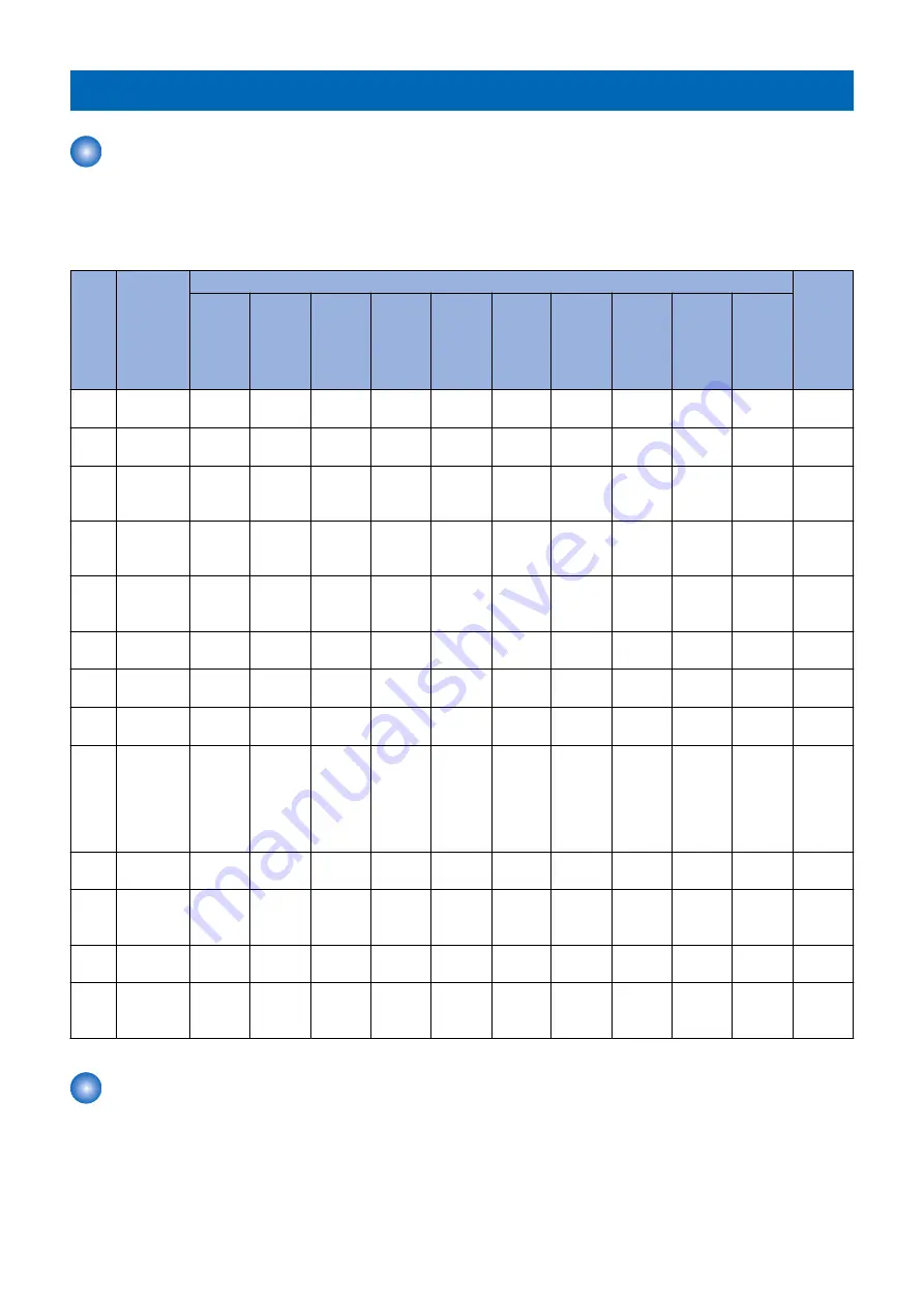
This machine have the following test print TYPE and you can judge the image failure that is checked as “Yes” in the following
image check items with each test print.
If the image failure occurred on normal output does not reappear on the test print, it may be caused by the PDL input or reader
side.
PG
TYPE
TYPE Pat-
tern
Items
Origina-
tor
Grada-
tion
Fog-
ging
Trans-
fer
Fault
Black
line
(Color
line)
White
line
Uneven
Density
Uneven
Density
at the
Front /
Rea
Right
Angle
Straight
Lines
Color
dis-
place-
ment
0
Normal
copy / print
----
1to3
---(For
R&D)
----
4
16 grada-
tions
Yes
Yes
Yes
Yes
Main
control-
ler PCB
5
Full half-
tone
Yes
Yes
Yes
Yes
Yes
Main
control-
ler PCB
6
Grid
Yes
Yes
Yes
Main
control-
ler PCB
7
---(For
R&D)
----
8
Half-tone /
Patch
Yes
Yes
Yes
Yes
Yes
9
---(For
R&D)
----
10
MCYBk
horizontal
stripes
(sub scan-
ning direc-
tion)
Yes
Yes
Yes
Main
control-
ler PCB
11
---(For
R&D)
----
12
MCYBk 64-
gradation
Yes
Yes
Yes
Main
control-
ler PCB
13
---(For
R&D)
----
14
Full color
16-grada-
tion
Yes
Yes
Main
control-
ler PCB
Steps to select the test print TYPE
1. Set the number of print, paper size etc.
2. Select: COPIER > TEST > PG.
3. Select: COPIER > TEST > PG > TYPE.
4. Enter the desired TYPE number and press OK key.
5. Select the corresponding color (setting 1 means output) in COLOR-Y/M/C/K.
6. Set the density in DENS-Y/M/C/K (this is enabled for TYPE=5 only).
6. Troubleshooting
402
Summary of Contents for imageRUNNER ADVANCE C3330 Series
Page 1: ...Revision 7 0 imageRUNNER ADVANCE C3330 C3325 C3320 Series Service Manual ...
Page 18: ...Product Overview 1 Product Lineup 7 Features 11 Specifications 17 Parts Name 26 ...
Page 518: ...Error Jam Alarm 7 Overview 507 Error Code 511 Jam Code 617 Alarm Code 624 ...
Page 1020: ...9 Installation 1008 ...
Page 1022: ...2 Perform steps 3 to 5 in each cassette 9 Installation 1010 ...
Page 1024: ...5 6 Checking the Contents Cassette Feeding Unit 1x 3x 2x 1x 9 Installation 1012 ...
Page 1027: ...3 4 NOTE The removed cover will be used in step 6 5 2x 2x 9 Installation 1015 ...
Page 1046: ...When the Kit Is Not Used 1 2 Close the Cassette 2 When the Kit Is Used 1 9 Installation 1034 ...
Page 1068: ... Removing the Covers 1 2x 2 1x 9 Installation 1056 ...
Page 1070: ...3 1x 1x 9 Installation 1058 ...
Page 1083: ...6 7 TP M4x8 2x 2x 9 Installation 1071 ...
Page 1084: ...When Installing the USB Keyboard 1 Cap Cover Wire Saddle 9 Installation 1072 ...
Page 1129: ...9 2x 10 2x 11 9 Installation 1117 ...
Page 1135: ...Remove the covers 1 ws 2x 2 1x 9 Installation 1123 ...
Page 1140: ...2 2x 3 Connect the power plug to the outlet 4 Turn ON the power switch 9 Installation 1128 ...
Page 1176: ... A 2x Installing the Covers 1 1x 2 2x 9 Installation 1164 ...
Page 1190: ...14 Install the Cable Guide to the HDD Frame 4 Hooks 1 Boss 9 Installation 1178 ...


