


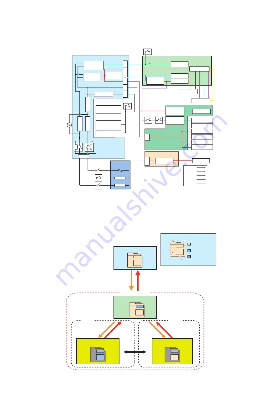
■ Power supply
● Internal power supply
Buffer Path PCB
Main Controller PCB
Fixing Unit
Low Voltage Power Supply PCB
DC Controller PCB
Main Power SW
3.3V
3.3V
3.3V
24V
24V
24V
12V
5V
5V
Interlock SW
Dehumidification SW
Interlock SW
24V
IL_SW
Temperature fuse
Main Heater
Sub Heater
24V
IL_SW
24V
5V
24V 5V
12V
6V
RMT_RLY1,2
(DCON Cont)
F
u
se
8
A
F
u
se
8
A
F
u
se
1
5
A
Fuse 3.15A
All-night
Circuit
RCON
Non-all-night
Circuit
24V AC/DC
CPU, ASIC
Laser
ADF
Reader
CassettePedestal
Inner FIN
Motors
3.3V
Power Supply
DC/DC
3.3V
Power Supply
DC/DC
Fans
High Voltage
External FIN
Cassete Pedestal
Cassette Heater
Reader Heater
3.3V All-night
Power Supply
AC/DC
24V
12V
5V
3.3V
6V
Inside Heater
J3
0
3
J3
0
6
J3
1
3
J3
2
1
J3
1
5
J302
J1
0
0
J1
1
8
6
Host Machine
Cassette Heater
Non-all-night
Circuit
5V
Power Supply
DC/DC
24V
Power Supply
AC/DC
12V
Power Supply
AC/DC
■ Energy Saving Function
● Overview
There are "Standby" mode and "Sleep" mode as the power supply mode of this machine.
Further, "Sleep" mode is divided into the followings: "Sleep Standby", "Sleep 1", and "Deep Sleep".
Deep Sleep
Sleep 1
Job end
Job end
Job submission
Energy Use
“High”
Energy Use
“Low”
Sleep Standby
Sleep Mode
Standby
Reader Control panel
Engine
Main Controler
State of power
supply ON
Energy Saving
State of power
supply OFF
Job submission
[Energy Saver] key is turned on
[Energy Saver] key is turned off
or
A specified period of time has passed
2. Technology
138
Summary of Contents for imageRUNNER ADVANCE C3330 Series
Page 1: ...Revision 7 0 imageRUNNER ADVANCE C3330 C3325 C3320 Series Service Manual ...
Page 18: ...Product Overview 1 Product Lineup 7 Features 11 Specifications 17 Parts Name 26 ...
Page 518: ...Error Jam Alarm 7 Overview 507 Error Code 511 Jam Code 617 Alarm Code 624 ...
Page 1020: ...9 Installation 1008 ...
Page 1022: ...2 Perform steps 3 to 5 in each cassette 9 Installation 1010 ...
Page 1024: ...5 6 Checking the Contents Cassette Feeding Unit 1x 3x 2x 1x 9 Installation 1012 ...
Page 1027: ...3 4 NOTE The removed cover will be used in step 6 5 2x 2x 9 Installation 1015 ...
Page 1046: ...When the Kit Is Not Used 1 2 Close the Cassette 2 When the Kit Is Used 1 9 Installation 1034 ...
Page 1068: ... Removing the Covers 1 2x 2 1x 9 Installation 1056 ...
Page 1070: ...3 1x 1x 9 Installation 1058 ...
Page 1083: ...6 7 TP M4x8 2x 2x 9 Installation 1071 ...
Page 1084: ...When Installing the USB Keyboard 1 Cap Cover Wire Saddle 9 Installation 1072 ...
Page 1129: ...9 2x 10 2x 11 9 Installation 1117 ...
Page 1135: ...Remove the covers 1 ws 2x 2 1x 9 Installation 1123 ...
Page 1140: ...2 2x 3 Connect the power plug to the outlet 4 Turn ON the power switch 9 Installation 1128 ...
Page 1176: ... A 2x Installing the Covers 1 1x 2 2x 9 Installation 1164 ...
Page 1190: ...14 Install the Cable Guide to the HDD Frame 4 Hooks 1 Boss 9 Installation 1178 ...


