


● System Manager Linkage (automatic ID allocation to System Managers)
SSO provided the automated function conventionally on Security Agent (hereinafter "SA") to authenticate System Manager by
allocating IDs set on SA to domain authentication managers (users belonging to Canon Peripheral Admins group). However,
User authentication does not support this function.
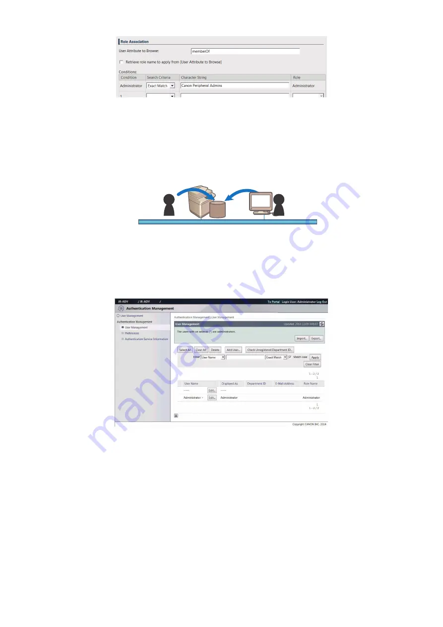
● Local device authentication
It is one of the user authentication methods using User Authentication, and is used for an device on a stand-alone basis.
Remote user
Device
Local user
Register the user to be authenticated on the database in the device.
The User Management screen can be changed on the [Settings/ Registration] > [Management Settings] > [User Management]
> [Authentication Management] > [User Management] screen of the Remote UI (http://IP address of the device:8000/userauth/
List).
User Management screen
● Server authentication (Active Directory authentication)
It is one of the user authentication methods using SSO-H. User authentication is performed with the device linked with a domain
controller on the network in an Active Directory environment. It is a user authentication where the user is authenticated by the
domain on the network when the user logs into the device. In addition to users belonging to the domain that includes the device,
users belonging to domains that have a reliable relationship with the domain (multi-domain) can also be authenticated. The domain
name of the login destination can be selected by the users themselves upon login.
Using one of the options (Net Spot Accountant, imageWARE Accounting Manager, or imageWARE EMC Accounting
Management Plug-in) makes it possible to analyze/manage the device usage.
2. Technology
145
Summary of Contents for imageRUNNER ADVANCE C3330 Series
Page 1: ...Revision 7 0 imageRUNNER ADVANCE C3330 C3325 C3320 Series Service Manual ...
Page 18: ...Product Overview 1 Product Lineup 7 Features 11 Specifications 17 Parts Name 26 ...
Page 518: ...Error Jam Alarm 7 Overview 507 Error Code 511 Jam Code 617 Alarm Code 624 ...
Page 1020: ...9 Installation 1008 ...
Page 1022: ...2 Perform steps 3 to 5 in each cassette 9 Installation 1010 ...
Page 1024: ...5 6 Checking the Contents Cassette Feeding Unit 1x 3x 2x 1x 9 Installation 1012 ...
Page 1027: ...3 4 NOTE The removed cover will be used in step 6 5 2x 2x 9 Installation 1015 ...
Page 1046: ...When the Kit Is Not Used 1 2 Close the Cassette 2 When the Kit Is Used 1 9 Installation 1034 ...
Page 1068: ... Removing the Covers 1 2x 2 1x 9 Installation 1056 ...
Page 1070: ...3 1x 1x 9 Installation 1058 ...
Page 1083: ...6 7 TP M4x8 2x 2x 9 Installation 1071 ...
Page 1084: ...When Installing the USB Keyboard 1 Cap Cover Wire Saddle 9 Installation 1072 ...
Page 1129: ...9 2x 10 2x 11 9 Installation 1117 ...
Page 1135: ...Remove the covers 1 ws 2x 2 1x 9 Installation 1123 ...
Page 1140: ...2 2x 3 Connect the power plug to the outlet 4 Turn ON the power switch 9 Installation 1128 ...
Page 1176: ... A 2x Installing the Covers 1 1x 2 2x 9 Installation 1164 ...
Page 1190: ...14 Install the Cable Guide to the HDD Frame 4 Hooks 1 Boss 9 Installation 1178 ...


