


NOTE:
The toner container premature replacement detection function utilizes the Bottle New/Old Sensor, and does not work for
unidentified Toner Containers.
Control description
Display a message when the Toner Container
is removed
Suspend operation when the Toner Contain-
er is prematurely replaced
Complete
the toner re-
placement
Detection tim-
ing
When the Toner Container is removed before the
message "Replace the toner cartridge." (refer to
"Toner Level Detection") is displayed.
When the Toner Container is replaced before the
message "Replace the toner cartridge." (refer to
"Toner Level Detection") is displayed.
When it has
been detected
that the Toner
Container was
replaced cor-
rectly
Alert/
message dis-
played
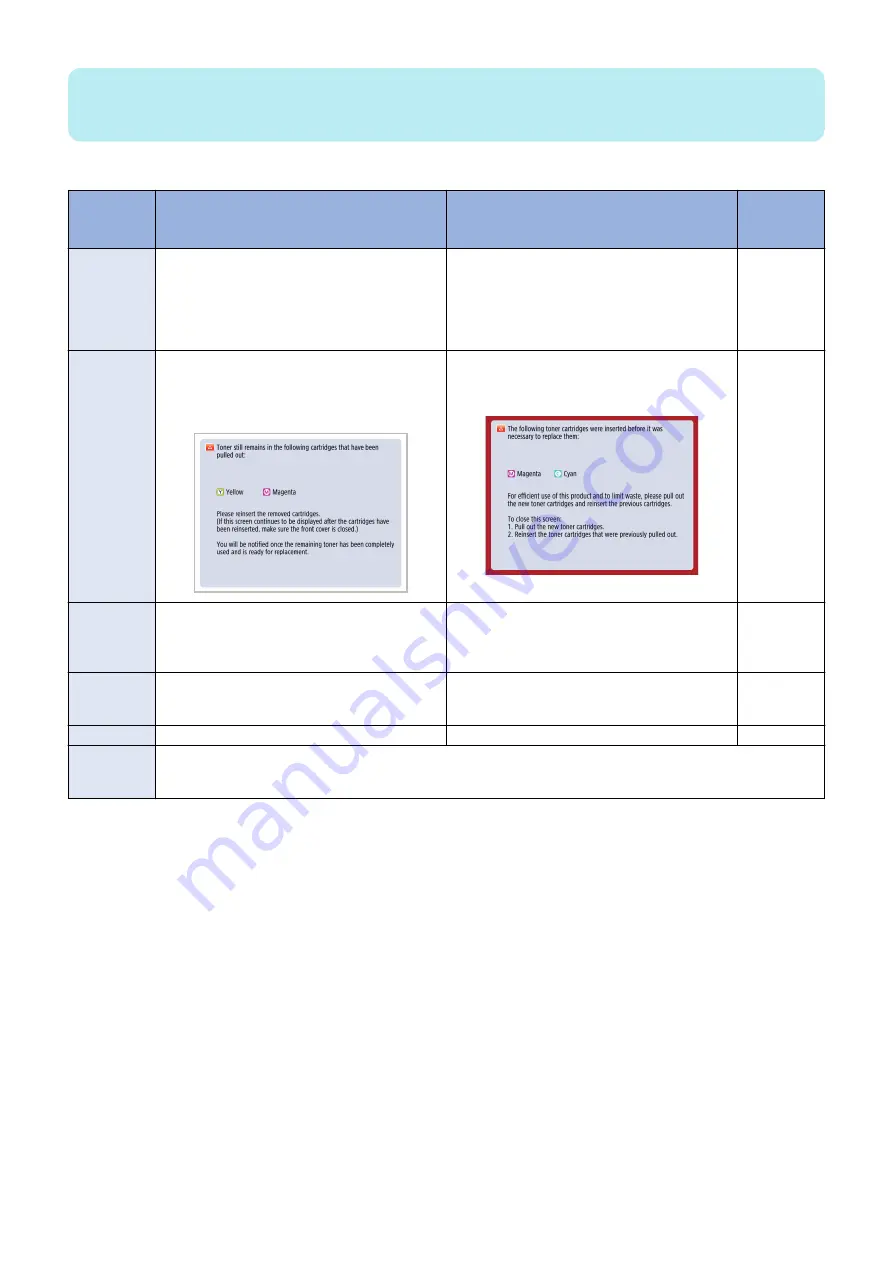
The message shown below is displayed with an
alert tone. *1
"The Toner Container of the color shown below that
can still be used has been removed."
The Toner Container of the color shown below that
can still be used has been replaced. Perform the
recovery procedure.
None
Operation
while the mes-
sage is dis-
played
Allowed
Operation is suspended.
-
How to clear
Install the removed container again, and close the
Front Cover of the host machine.
Install the Toner Container that had been installed
before the container was replaced, and close the
Front Cover of the host machine. *2
-
Default setting
ON (Display) *3
OFF (Not display) *4
-
Alarm code *5
10-0100-007x: Number of installations of new Toner Containers (each color)
10-0100-008x: Not used
10-0100-018x: Number of installations of unidentified Toner Bottles (each color)
*1: The alert tone generated when a message is displayed can be switched ON or OFF in the menu shown below.
Volume Control > Audible Tones > Non-Empty Toner Rplcd. Tone
*2: If the Toner Container that had been installed before the container was replaced cannot be installed, execute the following
service mode (Lv. 2) to clear the suspension of operation triggered by premature replacement of the Toner Container.
COPIER > OPTION > USER > TNRBEXGR
*3: It can be changed in the following service mode (Lv. 2).
COPIER > OPTION > USER > TNRBRMVR
*4: It can be changed in the following service mode (Lv. 2).
COPIER > OPTION > USER > TNRBEXGR
*5: A toner replacement completion alarm is not generated under the following conditions:
• The DC Controller PCB is replaced, and then a new Toner Bottle is installed before the power is turned ON.
• The DC Controller PCB is replaced, the power is turned ON with the Toner Bottle removed or the Front Door opened, and
then a new Toner Bottle is installed.
Related Control Panel menu
Volume Control > Audible Tones > Non-Empty Toner Rplcd. Tone
Related service mode
• ON/OFF of suspension of operation triggered by premature replacement of the Toner Container (Lv. 2)
COPIER > OPTION > USER > TNRBRMVR
2. Technology
91
Summary of Contents for imageRUNNER ADVANCE C3330 Series
Page 1: ...Revision 7 0 imageRUNNER ADVANCE C3330 C3325 C3320 Series Service Manual ...
Page 18: ...Product Overview 1 Product Lineup 7 Features 11 Specifications 17 Parts Name 26 ...
Page 518: ...Error Jam Alarm 7 Overview 507 Error Code 511 Jam Code 617 Alarm Code 624 ...
Page 1020: ...9 Installation 1008 ...
Page 1022: ...2 Perform steps 3 to 5 in each cassette 9 Installation 1010 ...
Page 1024: ...5 6 Checking the Contents Cassette Feeding Unit 1x 3x 2x 1x 9 Installation 1012 ...
Page 1027: ...3 4 NOTE The removed cover will be used in step 6 5 2x 2x 9 Installation 1015 ...
Page 1046: ...When the Kit Is Not Used 1 2 Close the Cassette 2 When the Kit Is Used 1 9 Installation 1034 ...
Page 1068: ... Removing the Covers 1 2x 2 1x 9 Installation 1056 ...
Page 1070: ...3 1x 1x 9 Installation 1058 ...
Page 1083: ...6 7 TP M4x8 2x 2x 9 Installation 1071 ...
Page 1084: ...When Installing the USB Keyboard 1 Cap Cover Wire Saddle 9 Installation 1072 ...
Page 1129: ...9 2x 10 2x 11 9 Installation 1117 ...
Page 1135: ...Remove the covers 1 ws 2x 2 1x 9 Installation 1123 ...
Page 1140: ...2 2x 3 Connect the power plug to the outlet 4 Turn ON the power switch 9 Installation 1128 ...
Page 1176: ... A 2x Installing the Covers 1 1x 2 2x 9 Installation 1164 ...
Page 1190: ...14 Install the Cable Guide to the HDD Frame 4 Hooks 1 Boss 9 Installation 1178 ...


