


■ Overall flow
1. Complete the device setting as a reference machine.
2. Set "1" in the following service mode to display "Service Mode Settings".
• Copier > Option > USER > SMD-EXPT
[0]: Hide the "Service Mode Settings" (Def.)
[1]: Display the "Service Mode Settings"
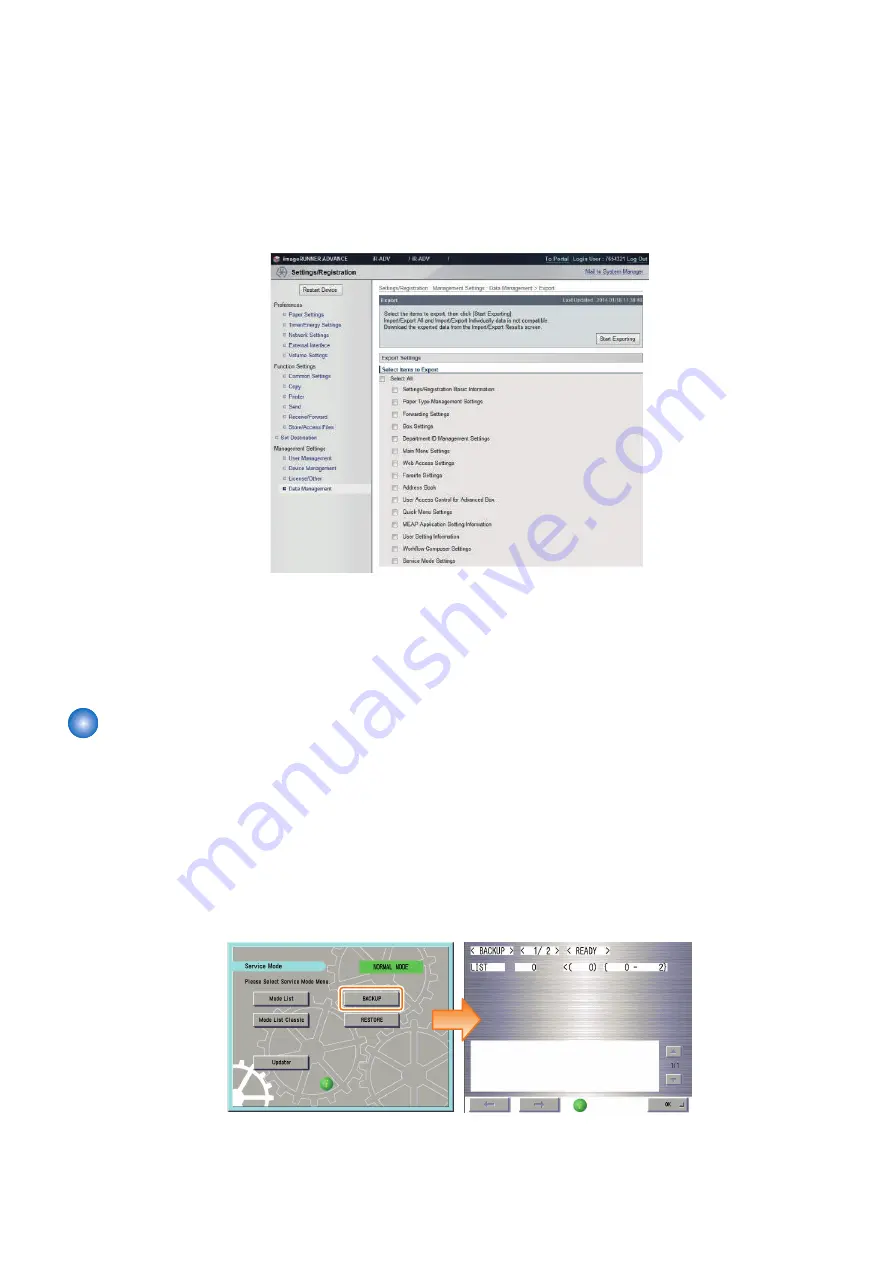
3. Export including "Service Mode Settings" from remote UI / touch panel display.
4. Copy the DCM file to the root folder of the USB device using a PC.
5. Connect the USB device to the copy destination machine.
6. Execute import by specifying the target files from [RESTORE] in service mode. (Refer to "
" of "Import/Export by Service Mode (External)")
Import/Export by Service Mode (External)
Import/export by service mode allows the selection between USB device and internal HDD for the save destination of DCM files.
The procedure of import/export when USB device is selected is shown below.
The DCM files to be exported contain only the items of "Service Mode Settings"
The DCM files to be imported can have been exported either by service mode or by "Settings/ registration.
■ Export Procedure
1. Connect the USB device.
2. Log in to service mode and press [BACKUP].
2. Technology
218
Summary of Contents for imageRUNNER ADVANCE C3330 Series
Page 1: ...Revision 7 0 imageRUNNER ADVANCE C3330 C3325 C3320 Series Service Manual ...
Page 18: ...Product Overview 1 Product Lineup 7 Features 11 Specifications 17 Parts Name 26 ...
Page 518: ...Error Jam Alarm 7 Overview 507 Error Code 511 Jam Code 617 Alarm Code 624 ...
Page 1020: ...9 Installation 1008 ...
Page 1022: ...2 Perform steps 3 to 5 in each cassette 9 Installation 1010 ...
Page 1024: ...5 6 Checking the Contents Cassette Feeding Unit 1x 3x 2x 1x 9 Installation 1012 ...
Page 1027: ...3 4 NOTE The removed cover will be used in step 6 5 2x 2x 9 Installation 1015 ...
Page 1046: ...When the Kit Is Not Used 1 2 Close the Cassette 2 When the Kit Is Used 1 9 Installation 1034 ...
Page 1068: ... Removing the Covers 1 2x 2 1x 9 Installation 1056 ...
Page 1070: ...3 1x 1x 9 Installation 1058 ...
Page 1083: ...6 7 TP M4x8 2x 2x 9 Installation 1071 ...
Page 1084: ...When Installing the USB Keyboard 1 Cap Cover Wire Saddle 9 Installation 1072 ...
Page 1129: ...9 2x 10 2x 11 9 Installation 1117 ...
Page 1135: ...Remove the covers 1 ws 2x 2 1x 9 Installation 1123 ...
Page 1140: ...2 2x 3 Connect the power plug to the outlet 4 Turn ON the power switch 9 Installation 1128 ...
Page 1176: ... A 2x Installing the Covers 1 1x 2 2x 9 Installation 1164 ...
Page 1190: ...14 Install the Cable Guide to the HDD Frame 4 Hooks 1 Boss 9 Installation 1178 ...


