


76
Rockwell Automation Publication 2198-UM002E-EN-P - February 2018
Chapter 4
Connector Data and Feature Descriptions
Contactor Enable Relay
The contactor-enable circuitry includes a relay-driven contact within the
2198-P
xxx
DC-bus power supply. The relay protects the Kinetix 5700 drive
system in the event of overloads or other fault conditions.
An AC three-phase mains contactor must be wired in series between the
branch circuit protection and the DC-bus power supply. In addition, the AC
three-phase contactor control string must be wired in series with the contactor-
enable relay at the contactor-enable (CED) connector. Refer to
for wiring examples.
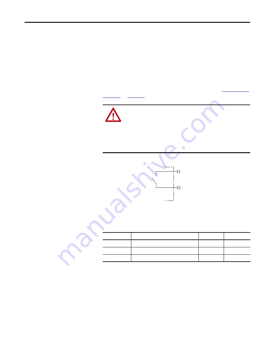
Figure 43 - Contactor-enable Relay Circuit
Surge suppression (diode, varistor module, RC module, or DC electronic
interface) is required across the auxiliary and main contactor coils.
Table 34 - Contactor-enable Relay Output Specifications
Motor Brake Circuit
The brake option is a spring-set holding brake that releases when voltage is
applied to the brake coil in the motor. The customer-supplied 24V power
supply drives the brake output through a solid-state relay. The dual-axis
inverters have separate brake circuits for each axis. The solid-state brake driver
circuit provides the following:
• Brake current-overload protection
• Brake over-voltage protection
ATTENTION:
Wiring the contactor-enable relay is required. To avoid personal
injury or damage to the drive, wire the contactor-enable relay into your
control string so that:
• three-phase power is removed and the DC-bus power supply is protected
under various fault conditions.
• three-phase power is never applied to the Kinetix 5700 drive system before
control power is applied.
CONT EN-
CONT EN+
Normally
Open
Relay
Kinetix 5700
Servo Drive
Attribute
Value
Min
Max
On-state current
Current flow when the relay is closed
–
1 A
On-state resistance
Contact resistance when the relay is closed
–
1
Ω
Off-state voltage
Voltage across the contacts when the relay is open
–
240V DC