


Rockwell Automation Publication 2198-UM002E-EN-P - February 2018
219
Troubleshoot the Kinetix 5700 Drive System
Chapter 7
FLT S55 – VEL ERROR
Excessive Velocity Error Fault
The velocity error of the velocity control
loop has exceeded the value given by
Velocity Error Tolerance for a time period
given by Velocity Error Tolerance Time.
• Check velocity loop tuning
• Reduce acceleration
• Verify sizing of the drive and motor
• Check motor power wiring
• Increase Velocity Error Tolerance and/or Velocity Error Tolerance
Time attribute values
Inverters
FLT S56 – OVERTORQUE LIMIT
Overtorque Limit Fault
Motor torque has risen above user
defined maximum torque level given by
Overtorque Limit for a time period given
by Overtorque Limit Time.
• Verify Torque Trim value
• Verify motion profile
• Verify sizing of the drive and motor
• Increase Overtorque Limit and/or Overtorque Limit Time
attribute values
Inverters
FLT S57 – UNDERTORQUE LIMIT
Undertorque Limit Fault
Motor torque has dropped below user
defined minimum torque level given by
Undertorque Limit for a time period given
by Undertorque Limit Time.
• Verify motion profile
• Verify sizing of the drive and motor
• Decrease Undertorque Limit and/or Undertorque Limit Time
attribute values
Inverters
FLT S61 – ENABLE INPUT
Enable Input Deactivated
The hardware enable input was
deactivated while the drive was enabled.
• Check drive enable input wiring
• Un-assign Enable as a digital input source
Inverters
DC-bus PS
iTRAK PS
(1) All modules in the same bus group assert a Bus Power Sharing Exception if they are enabled.
(2) When the Power Loss Threshold Attribute (ID#628) is set to zero, the default value of 23.1% is used, which is equivalent to 150V DC allowable DC-bus voltage droop from nominal (650V DC). To
calculate the percentage, use the following formula: Power Loss Threshold Attribute% = (650V DC - Allowable Voltage Drop)/(650V DC) *100%.
(3) Applies to all compatible feedback devices, except DSL encoder feedback.
(4) Applies to DSL and Hiperface feedback devices.
(5) Does not apply to induction motors in frequency control mode.
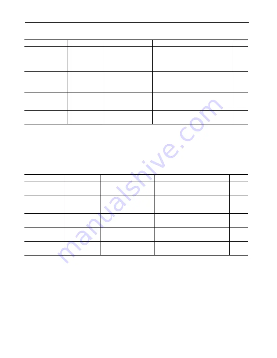
Table 95 - FLT S
xx
Fault Codes (continued)
Exception Code on Display
Exception Text
Problem
Possible Solutions
Module
Table 96 - FLT M
xx
Fault Codes
Exception Code on Display
Exception Text
Problem
Possible Solutions
Module
FLT M02 – MOTOR VOLTAGE
Motor Voltage Mismatch
Fault
The configured voltage of the drive is greater
than the motor rated voltage. For example, a
400V-class drive with a 200V-class motor.
Set the drive voltage to a lower value or replace motor with
voltage
rating that matches the drive.
Inverters
FLT M07 - FEEDBACK
INCREMENTAL COUNT
ERROR FAULT
Feedback Incremental Count
Error
The periodic check of the incremental encoder
position against the absolute encoder
position or Hall edges (when available)
indicates they are out of tolerance.
Verify the motor feedback wiring is correct and not open/
shorted/missing, use shielded cables, route feedback away from
potential noise sources, check system grounds, replace motor/
encoder.
Inverters
FLT M12 – POWER CYCLE FL
(1)
Converter Precharge
Overload Factory Limit Fault
The thermal model for the precharge resistor
detected that precharge capacity exceeded
the factory limit.
• Reduce the amount of modules in the same bus group
• Reduce the frequency of AC power cycling
• Remove capacitor modules
DC-bus PS
FLT M26 – RUNTIME ERROR
Runtime Error
The drive firmware encountered an
unrecoverable runtime error.
• Cycle control power
• Reset the drive
• Return drive for repair if fault continues
Inverters
DC-bus PS
iTRAK PS
FLT M28 – SAFETY COMM
(2)
Safety Module
Communication Error
Communication with the safety hardware
within the drive has failed.
• Cycle control power
• Reset the drive
• Return drive for repair if fault continues
Inverters
(1) All modules in the same bus group assert a Bus Power Sharing Exception if they are enabled.
(2) Applies to drives using integrated safety.