


264
Rockwell Automation Publication 2198-UM002E-EN-P - February 2018
Chapter 9
Kinetix 5700 Safe Torque-off Function
Table 138 - Dual-axis Inverter Integrated STO Specifications
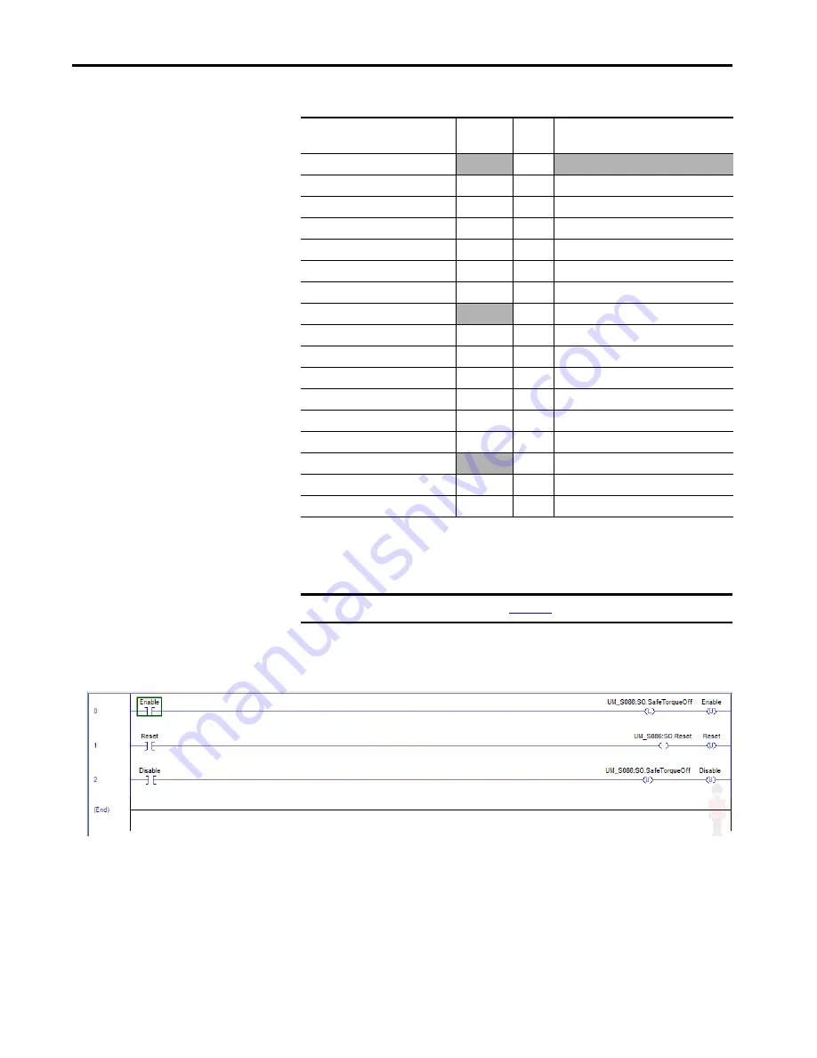
In this example, the SO.SafeTorqueOff bit permits torque when the bit is high.
Figure 115 - Safe Torque-off Function Safety Logic Example
Logix Designer Tag Name
Attribute
[bit]
Type
Description
SI.ConnectionStatus
(1)
(2)
(1) Bits not listed are always zero.
(2) ConnectionStatus is determined by the Safety Validator in the GuardLogix controller.
DINT
SI.RunMode
[0]
BOOL
Combinations of the RunMode and
SI.ConnectionFaulted
[1]
BOOL
ConnectionFaulted states
SI.Status1
(1)(3)
(3) The Status is sent from the drive to the controller using integrated safety protocol.
0x1A8
SINT
Inverter Axis 1
SI.TorqueDisabled1
[0]
BOOL
0 = Torque Permitted; 1 = Torque Disabled
SI.SafetyFault1
[6]
BOOL
1 = STO Fault present
SI.ResetRequired1
[7]
BOOL
1 = A reset is required
SI.Status2
SINT
Inverter Axis 2
SI.TorqueDisabled2
[0]
BOOL
0 = Torque Permitted; 1 = Torque Disabled
SI.SafetyFault2
[6]
BOOL
1 = STO Fault present
SI.ResetRequired2
[7]
BOOL
1 = A reset is required
SO.Command1
(4)
(4) The Command is sent from the controller to the drive using integrated safety protocol.
0x188
SINT
Inverter Axis 1
SO.SafeTorqueOff1
[0]
BOOL
0 = Disable Permit; 1 = Permit Torque
SO.Reset1
[7]
BOOL
0-->1 = Reset STO Fault
SO.Command2
SINT
Inverter Axis 2
SO.SafeTorqueOff2
[0]
BOOL
0 = Disable Permit; 1 = Permit Torque
SO.Reset2
[7]
BOOL
0-->1 = Reset STO Fault
IMPORTANT
Only the data listed in
is safety data with SIL 3 integrity.