


260
Rockwell Automation Publication 2198-UM002E-EN-P - February 2018
Chapter 9
Kinetix 5700 Safe Torque-off Function
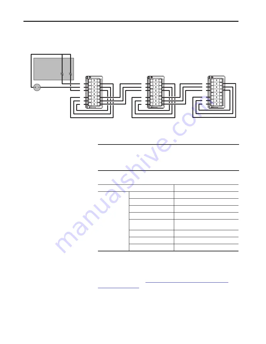
In this example, the cascaded STO wiring is for one dual-axis inverter
application with a single safety device for both axes.
Figure 114 - Cascaded STO Wiring - Dual-axis Inverter with Single Safety Device
Hardwired Safe Torque-off Electrical Specifications
Table 134 - Hardwired STO Electrical Specifications
For additional information regarding Allen-Bradley® safety products, including
safety relays, light curtain, and gate interlock applications, refer to the Safety
Products Catalog, website
http://www.rockwellautomation.com/global/
.
1
2
12
3
4
5
6
7
8
9
10
11
13
14
15
16
1
2
12
3
4
5
6
7
8
9
10
11
13
14
15
16
1
2
12
3
4
5
6
7
8
9
10
11
13
14
15
16
24V DC
SB+/NC
S1A
SCA
S2A
SB-
S1B
SCB
S2B
SB+/NC
S1A
SCA
S2A
SB-
S1B
SCB
S2B
SB+/NC
S1A
SCA
S2A
SB-
S1B
SCB
S2B
First Drive
Middle Drive
Last Drive
Dual-channel
Equivalent
Safety Device
IMPORTANT
To maintain their safety rating, Kinetix 5700 inverters must be installed
inside protected control panels or cabinets appropriate for the
environmental conditions of the industrial location. The protection class of
the panel or cabinet must be IP54 or higher.
Attribute
Value
Safety inputs
(per channel)
Input current
< 10 mA
Input ON voltage range
18…26.4V DC
Input OFF voltage, max
5V DC
Input ON current, per input, max
10 mA, each drive
(2)
(2) The maximum number of drives cascaded with safe torque-off wiring is 50.
Input OFF current, max
(@ V in < 5V DC)
2 mA
Pulse rejection width
700
μ
s
External power supply
(1)
(1) SELV or PELV rated power supplies must be used to energize external safety devices connected to the Kinetix 5700 safety inputs.
SELV/PELV
Input type
Optically isolated and reverse voltage protected