


160
Rockwell Automation Publication 2198-UM002E-EN-P - February 2018
Chapter 6
Configure and Start the Kinetix 5700 Drive System
Table 90 - Motion Safety Definitions
The Safety Network Number (SNN) field populates automatically
when the Connection mode includes an integrated Motion and Safety
or Safety-only connection. For a detailed explanation of the safety
network number, refer to the appropriate GuardLogix controller
publication as defined in
.
5.
Click OK to close the Module Definition dialog box.
Configure the Power and Safety Categories
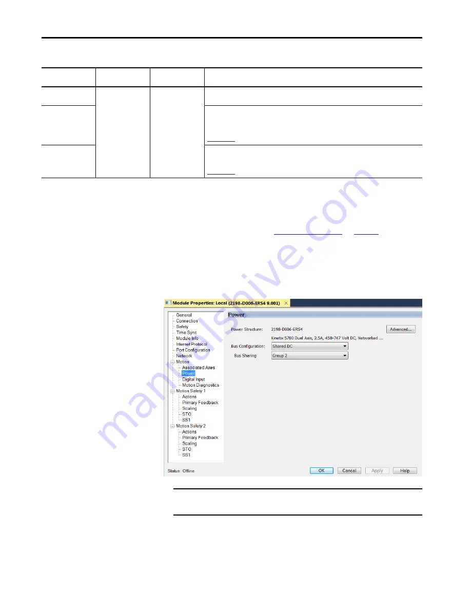
1.
Click the Power category.
Motion Safety Mode
Safety Application
Mode
Module Connection
Options
Description
Safe Stop Only -
No Feedback
Networked
• Motion and Safety
• Safety Only
2198-
xxxx
-ERS4 inverters with the same integrated safety function that is associated with the
2198-
xxxx
-ERS3 inverters.
Single Feedback
Monitoring
Primary feedback is used in the safety object for safe monitoring. The feedback can be a SIL rated
Hiperface DSL encoder, for example, a VPL-B1003P-Q or W motor used in the DSL Feedback port. This
can also be a Sine/Cosine or EnDat device, for example, an MPL-B310P-M motor used in the Universal
Feedback port. See the Kinetix 5700 Safe Monitor Functions Safety Reference Manual, publication
, to evaluate SIL levels possible with a single feedback device.
Dual Feedback
Monitoring
In addition to primary feedback, an external feedback device is used to improve SIL levels. For
example, the Bulletin 842HR type encoder can be used in the Universal Feedback port as a Sine/
Cosine device. See the Kinetix 5700 Safe Monitor Functions Safety Reference Manual, publication
, to evaluate SIL levels possible with two feedback devices.
IMPORTANT
The Logix Designer application enforces shared-bus configuration rules
for Kinetix 5700 drives.