


2.2 Troubleshooting with Error Messages
VJ1324E-M-02
2.2.3 Errors Requiring Reboot
P.2-21
2
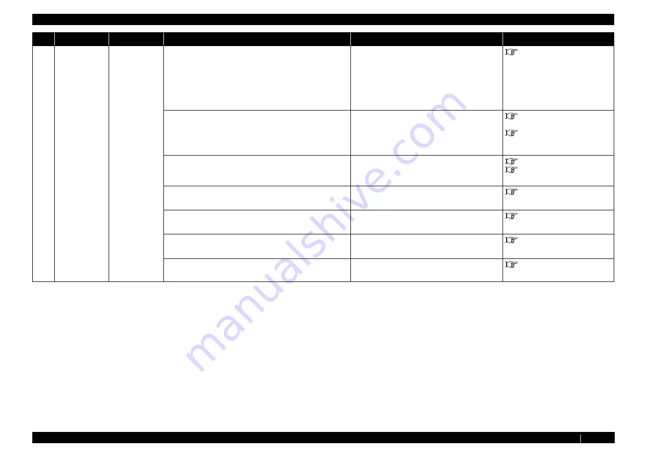
E 067Err
PF encoder
Abnormal
condition in
media feed
amount (X-
axis) during
printer
operation.
Displayed if
there is no
feedback from
encoder.
1. Check error history from "Test7: Record" of self-
diagnosis function.
1.
-
2. Set the number of endurance running cycles to 50 or
more from "Life: PF motor" of self-diagnosis
function, and check if "PF encoder error" occurs.
Check the connection of the following MAIN
board Assy connectors:
•
PF motor cable Assy connector
•
PF encoder Assy connector
3. Check "Encoder: PF" from "Test5: Encoder" of self-
diagnosis function.
If NG, check the connection of MAIN board
Assy connector.
"5.5.4 Sensor Menu" p.5-12
"3.4.4 Replacing MAIN Board
4. Is the area around PF encoder contaminated?
Clean around PF encoder.
Replace PF encoder if it is damaged.
5. Check if MAIN Power Board normally supplies
DC24V.
Replace the power board Assy if it is
damaged.
6. PF motor Assy may be damaged.
Replace PF motor Assy .
7. MAIN board Assy may be defective.
Replace MAIN board Assy .
No.
Message
Symptoms
Check Item
Action
Reference
Summary of Contents for ValueJet VJ-1324
Page 1: ...VJ1324E M 02 VJ 1324 Full Color Inkjet Printer MAINTENANCE MANUAL ...
Page 86: ...P 3 4 VJ1324E M 02 3 13 7 Replacing Peripheral Devices of VJ Take Up Unit Motor Assy 3 179 ...
Page 409: ...P 10 1 VJ1324E M 02 10 Appendix 10 1 Introduction 10 2 10 2 Maintenance Part List 10 2 ...
Page 419: ......
Page 420: ......