


5 Operation Panel Switches in Operation Mode
MITSUBISHI CNC
II - 22
5.7 Manual Pulse Generator
5.8 Cycle Start and Feed Hold
The CYCLE START switch becomes effective when the switch is turned ON, then OFF.
Use the FEED HOLD switch to temporarily stop automatic operation (for example, deceleration stop of the control axis
during automatic operation). To restart operation, use the CYCLE START switch.
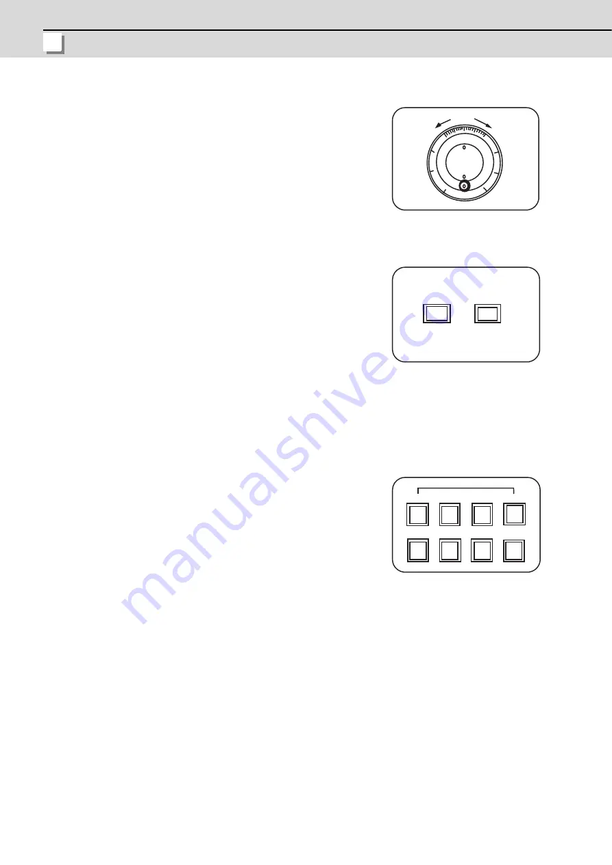
5.9 Feed Axis Selection
In the manual handle mode, fine feed of the machine can be made by turning the
manual pulse generator.
The manual pulse generator has 100 graduations per revolution and outputs one
pulse per graduation. The travel distance per pulse is set by using the HANDLE/
INCREMENTAL MAGNIFICATION switch.
Use the CYCLE START switch to start automatic operation (memory, tape, or
MDI). Automatic operation is executed by turning ON the switch. Use also the
switch for restart from stop by the FEED HOLD switch or the automatic operation
stop state.
Use the FEED AXIS SELECT switch to start the controlled axis during manual
operation. While the FEED AXIS SELECT switch is held ON, the selected
controlled axis is moved. When the switch is turned OFF, the controlled axis
movement stops.
HANDLE
0 0
+
-
0
1
1 0
1
0
7 2
FEED HOLD
CYCLE START
FEED AXIS SELECT
+X
-X
+Y
-Y
+Z
-Z
+4
-4
Summary of Contents for E70 Series
Page 1: ......
Page 3: ......
Page 9: ......
Page 11: ......
Page 13: ......
Page 15: ......
Page 24: ...I SCREEN OPERATIONS ...
Page 25: ......
Page 26: ...I 1 1 Operating the Setting and Display Unit ...
Page 57: ...1 Operating the Setting and Display Unit MITSUBISHI CNC I 32 ...
Page 58: ...I 33 2 Monitor Screens ...
Page 139: ...2 Monitor Screens MITSUBISHI CNC I 114 ...
Page 140: ...I 115 3 Setup Screens ...
Page 232: ...I 207 4 Edit Screens ...
Page 314: ...I 289 5 Diagnosis Screens ...
Page 355: ...5 Diagnosis Screens MITSUBISHI CNC I 330 ...
Page 356: ...I 331 6 Maintenance Screens ...
Page 436: ...II MACHINE OPERATIONS ...
Page 437: ......
Page 439: ...MITSUBISHI CNC II 2 ...
Page 440: ...II 3 1 Operation State ...
Page 444: ...II 7 2 Indicator Lamps ...
Page 446: ...II 9 3 Reset Switch and Emergency Stop Button ...
Page 448: ...II 11 4 Operation Mode ...
Page 456: ...II 19 5 Operation Panel Switches in Operation Mode ...
Page 460: ...II 23 6 Operation Panel Switch Functions ...
Page 495: ...6 Operation Panel Switch Functions MITSUBISHI CNC II 58 ...
Page 496: ...II 59 7 Other Functions ...
Page 509: ...7 Other Functions MITSUBISHI CNC II 72 ...
Page 510: ...III MAINTENANCE ...
Page 511: ......
Page 512: ...III 1 1 Daily Maintenance and Periodic Inspection and Maintenance ...
Page 515: ...1 Daily Maintenance and Periodic Inspection and Maintenance MITSUBISHI CNC III 4 ...
Page 516: ...III 5 2 Hardware Replacement Methods ...
Page 531: ...2 Hardware Replacement Methods MITSUBISHI CNC III 20 ...
Page 532: ...IV APPENDIXES ...
Page 533: ......
Page 534: ...IV 1 Appendix 1 List of Function Codes ...
Page 536: ...IV 3 Appendix 2 Table of Command Value Ranges ...
Page 543: ...Appendix 2 Table of Command Value Ranges MITSUBISHI CNC IV 10 ...
Page 544: ...IV 11 Appendix 3 Circular Cutting Radius Error ...
Page 546: ...IV 13 Appendix 4 Registering Editing the Fixed Cycle Program ...
Page 561: ...Appendix 4 Registering Editing the Fixed Cycle Program MITSUBISHI CNC IV 28 ...
Page 562: ...IV 29 Appendix 5 RS 232C I O Device Parameter Setting Examples ...
Page 564: ...IV 31 Appendix 6 Explanation of Alarms ...
Page 678: ...IV 145 Appendix 7 Operation Messages ...
Page 699: ...Appendix 7 Operation Messages MITSUBISHI CNC IV 166 ...
Page 700: ...IV 167 Appendix 8 User Parameters ...
Page 777: ...Appendix 8 User Parameters MITSUBISHI CNC IV 244 ...
Page 782: ......


