background image


5-92 Image Optimization 

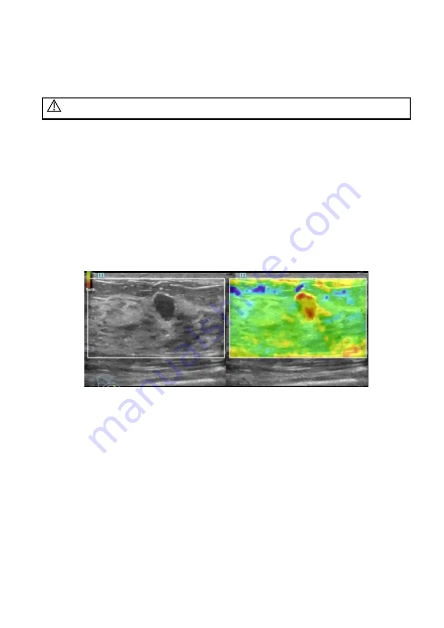
5.14  Elastography 

5.14.1  Strain Elastography 

CAUTION:


It is provided for reference, not for confirming a diagnosis.


It is produced based on the slight manual-pressure or human respiration in 2D real-time mode. The 
tissue hardness of the mass can be determined by the image color and brightness. Besides, the relative 
tissue hardness is displayed in quantitative manners.   


The strain elastography is an option. Only the probes support the strain elastography: 


The L11-3U/L14-6WU/L14-5WU probes support the strain elastography. 


The L9-3U probe supports the strain elastography. 


The L20-5U probe supports the strain elastography. 


The V11-3HU/DE10-3U probe supports the strain elastography. 

5.14.1.1  Basic Procedure for Strain Elastography 

1.  Perform 2D scan to locate the region.   

2.  Tap [Elasto]

[Strain] on the touch screen. Assign a user-defined key for Elastography via: 

[Setup]

[System Preset]

[Key Config]. Adjust ROI according to the lesion size.   


  Press the probe according to the experiences and actual situation. 

  Adjust the image parameters to obtain optimized image and necessary information. 

  Adjust the image parameters to obtain optimized image. 

  Do measurement or add comment/body mark to the image if necessary. 

3.  Evaluate the result based on the information above. 

4.  Press <B> to return to B mode or another mode. 

5.14.1.2  Enter/Exit 

  Enter 

Select [Elasto]

[Strain] on the touch screen to enter the mode. 

The system displays two dual B+E windows in real time. The left one is 2D image, and the right one 
is elasto image. 

  Exit 

Press <B> or tap [Elasto] to exit, and then return to B mode. 

5.14.1.3  Strain Curve 

The screen displays the pressure curve in real-time: 

Summary of Contents for Resona 7

Page 1: ...Resona 7 Resona 7CV Resona 7EXP Resona 7S Resona 7OB Diagnostic Ultrasound System Operator s Manual Basic Volume...

Page 2: ......

Page 3: ...duction of Each Unit 2 9 2 6 I O Panel 2 11 2 7 Power Supply Panel 2 12 2 8 Physio Unit Panel ECG 2 13 2 9 Control Panel 2 14 2 10 Symbols 2 18 3 System Preparation 3 1 3 1 Moving Position the System...

Page 4: ...6 4 Cine Review 6 3 6 5 Image Compare 6 5 6 6 Cine Saving 6 6 6 7 Preset 6 6 7 Physiological Unit Signal 7 1 7 1 ECG 7 2 7 2 PCG 7 3 7 3 ECG PCG Review 7 5 7 4 Respiratory Wave 7 5 7 5 Parameter Descr...

Page 5: ...3 Needle Navigation Guiding 13 47 13 4 Middle Line 13 59 14 DVR Recording 14 1 14 1 DVR Recording 14 1 14 2 Send Image 14 1 14 3 DVR Video Replay 14 2 15 Acoustic Output 15 1 15 1 Concerns with Bioeff...

Page 6: ...iv Appendix D Ultrasound Gel Heater D 1 Appendix E Electrical Safety Inspection E 1 Appendix F List of Vocal Order F 1...

Page 7: ...er countries All other trademarks that appear in this manual are used only for informational or editorial purposes They are the property of their respective owners Responsibility on the Manufacturer P...

Page 8: ...f the product or the use of parts or accessories not approved by Mindray or repairs by people other than Mindray authorized personnel This warranty shall not extend to Malfunction or damage caused by...

Page 9: ...12th Road South High tech industrial park Nanshan Shenzhen 518057 P R China Website www mindray com E mail Address service mindray com Tel 86 755 81888998 Fax 86 755 26582680 Manufacturer Mindray DS...

Page 10: ...e liable for the results of diagnostic procedures 7 Important data must be backed up on external memory media 8 Mindray shall not be liable for loss of data stored in the memory of this system caused...

Page 11: ...Operator s Manual Advanced Volume Operator s Manual Acoustic Power Data and Surface Temperature Data Contains data tables of acoustic output for transducers Operation Note Contains a quick guide for...

Page 12: ...ts indicate buttons knobs and other controls on the control panel or on the keyboard Items in menu or buttons in dialog box square brackets indicate items in menus on the soft menu or buttons in dialo...

Page 13: ...sterilization method s recommended by manufacturer The devices recommended by the manufacturer According to the degree of safety of application in the presence of a FLAMMABLE ANESTHETIC MIXTURE WITH...

Page 14: ...ous injury WARNING Indicates a potentially hazardous situation that if not avoided could result in death or serious injury CAUTION Indicates a potentially hazardous situation that if not avoided may r...

Page 15: ...asound system meets the requirement of the local medical device electrical regulation like enclosure leakage current should be no more than 500uA of IEC60601 1 3rd chapter 16 and the responsibility is...

Page 16: ...wer for the recommended peripheral devices Do not connect other devices to the outlet otherwise the rated output power may be exceeded and failure may be resulted Maximum output power of the outlet is...

Page 17: ...ase take care to prevent the system from toppling 4 If the circuit protector is tripped it indicates that the system or a peripheral device was improperly shut down and the system is unstable You cann...

Page 18: ...ansporting this system quickly from a cold place to a warm place otherwise condensation or water droplets may form allowing a short circuit and possible electric shock Note 1 DO NOT use the system in...

Page 19: ...ply of the system during printing file storage or invoking other system operations An interrupted process may not be completed and can become lost or corrupted 15 The iScape feature constructs a singl...

Page 20: ...only Do not use if integrity of packaging violated or if expiration date has passed Please use the disposable components compliant with the relevant local regulations 8 Please use the disinfection or...

Page 21: ...10 4U C6 2GU C11 3U under the following conditions Ambient temperature 0 C 40 C relative humidity 20 85 no condensation atmospheric pressure 700 hPa 1060 hPa 4 Use the probe D8 4U under the following...

Page 22: ...E10 3WU under the following conditions Ambient temperature 18 C 30 C relative humidity 30 85 no condensation atmospheric pressure 700 hPa 1060 hPa 9 Use the probes D8 2U under the following conditions...

Page 23: ...therwise the system may slide resulting in personal injury or the system malfunction Two persons are required to move the system over a sloped surface b Do not sit on the system c DO NOT push the syst...

Page 24: ......

Page 25: ...ional superficial cardiac adult cardiac pediatric trans esoph cardiac peripheral vessel and urology exams 2 2 Contraindication The diagnostic ultrasound system is not intended for ophthalmic use 2 3 P...

Page 26: ...including the probe weight less than 134 5 Kg TDI QA Special imaging Ultrasound Fusion Imaging Strain Elastography iPage STIC SCV Smart Volume Niche iLive V Flow RIMT Fusion RESP Component Voltage 10...

Page 27: ...Body surface DE10 3U Intracavitary Fetal Trans rectal Trans vaginal Transvaginal L14 6WU Linear Abdominal Pediatric Small organ breast thyroid testes Musculo skeletal Conventional Musculo skeletal Sup...

Page 28: ...3TU Phase Trans esoph Cardiac Transesophagel P7 3Ts Phase Trans esoph Cardiac Transesophagel L16 4HU Linear Abdominal Intra operative Intraoperative includes abdominal thoracic and vascular Pediatric...

Page 29: ...7G 18G C5 1U SC6 1U NGB 022 Metal needle detachable 25 35 45 Metal 14G 16G 18G 20G 22G V11 3HU NGB 025 Metal needle undetachable 1 2 Metal 16G 17G 18G L11 3U NGB 026 Metal needle detachable 40 50 60 M...

Page 30: ...imaging module 1 magnetic navigation controller 1 magnetic generator and 1 fusion imaging sensor configured with the fusion imaging 12 Motion abdomen sensor bracket configured with the Fusion RESP Co...

Page 31: ...red with 4D and Obstetrics Package 37 iScape View panoramic imaging assembly 38 Free Xros M 39 Free Xros CM 40 Tissue Doppler Imaging TDI configured with Cardiology Package 41 TDI QA configured with T...

Page 32: ...VQS configured with the vascular package 71 iWorks 72 iNeedle 73 DVR Module 74 UltraView UltraView TDI QA UltraView Tissue Tracking QA UltraView Stress Echo UltraView Niche UltraView iLive UltraView i...

Page 33: ...OTE the disks of the printers listed above are installed in the system For other types of the printer the user can install on their own WARNING This system complies with IEC60601 1 2 2007 and its RF e...

Page 34: ...robe 11 Rotatable knob on the control panel Lock or unlock the move of the control panel 12 Ascending descending button The button to ascend or descend the system 13 Control panel Key pressing operato...

Page 35: ...definition multimedia interface 3 Network port 4 VGA VGA signal output 5 S Video S Video signal output 6 Audio signal output port left channel 7 Audio signal output port right channel 8 12 V indicato...

Page 36: ...tput Supply power for optional peripheral devices 2 Circuit breaker Used for switching off on the power supply 3 Power inlet AC power inlet 4 Equipotential terminal Used for equipotential connection t...

Page 37: ...rophone input 3 Used for connecting a pencil probe 4 Connects to ECG leads to directly obtain the ECG signals of the patient Connects the signal output port of ECG monitoring device 5 Reserved port Re...

Page 38: ...he disk 2 A power Adjust the acoustic power 3 Volume Adjust the volume 4 Adjust the corresponding functions on the touch screen 5 P1 P4 Undefined Button set by the user in preset See Chapter 12 Setup...

Page 39: ...e around X axis 18 CW Enter CW mode 19 Power Enter Power mode 20 Dual Enter Dual mode in Non Dual mode Press to switch between the two interfaces in the Dual mode 21 B Press to enter B mode Rotate to...

Page 40: ...he screen 9 Direction keys Move the cursor one letter each time or select the ambient one in a selectable area 10 Arrow Press the key to turn to the symbol of arrow 11 Body Mark Press the key to enter...

Page 41: ...on the key For the alphabet keys A Z press Shift key to enter the current letter in a different case Alt Gr key Combined with other letter keys Alt Gr can be used for entering other languages Press A...

Page 42: ...A VGA input 13 S VIDEO Reserved used for separate video output 14 AUDIO Stereo audio output 15 HDMI High definition multimedia interface 16 Microphone input jack 17 When the lever located at the botto...

Page 43: ...d system or using peripherals other than permitted by Mindray make sure the overall leakage current of peripherals and the ultrasound system meets the requirement of the local medical device electrica...

Page 44: ...ystem and other electrical equipment WARNING 1 Be sure to connect the equipotential wire before inserting the power plug into the receptacle be sure to pull out the power plug from the receptacle befo...

Page 45: ...ing and disinfection 7 No miscellaneous odds and ends are allowed to be attached or affixed to the control panel 8 Ensure that all connections are free from damage and remain clear of foreign object b...

Page 46: ...h panel to see the option Shut down To power off the system normally Standby To enter standby status Cancel To cancel the operation If you will not use the system for a long period of time you should...

Page 47: ...When the system enters the standby status if need to power off Press the power button to exit the powering off status and then power off the system NOTE If you will not use the system for a long peri...

Page 48: ...E Take care not to trap your hands when adjusting the monitor up and down Rotate the monitor Upper arm rotation The monitor can be rotated 90 along with the supporting arm or the supporting arm can be...

Page 49: ...djustment Monitoring the brightness and contrast adjustment is one of the most important factors for proper image qualities If set incorrectly the gain TGC dynamic range or even acoustic output have t...

Page 50: ...to avoid excessively bending and damaging the cable 4 Only use the transducers provided by Mindray Aftermarket transducers may result in damage or cause a fire 3 5 1 Connecting a Probe WARNING The tr...

Page 51: ...port slowly and carefully while keeping the socket position upward 2 Move the probe adapter locking lever to vertical position through 90 clockwise and lock it 3 Stick the TEE probe connector to TEE p...

Page 52: ...USB memory device A sound is heard when removing the USB memory device 3 6 2 Connecting a Footswitch WARNING Do not connect two or more footswitches to the main unit otherwise it may lead to the malfu...

Page 53: ...Power on the system and the printer 3 Put the installation optical disk of the printer driver into the drive 4 Install the printer driver Select Setup Print Add Printer NOTE all the operations are fi...

Page 54: ...et printer and click Next the system tries to connect to this printer 4 When the connection is successful the system prompts the dialogue box click Next according to the screen tips and then click Fin...

Page 55: ...d for details It is unnecessary to install drivers for the printers already listed 4 Add a print service 1 Open the Setup Print screen 2 Click Add Service to enter the page 3 Select the service type a...

Page 56: ...mble the control panel to remove the rectangle caps The ultrasound system is equipped with five rectangle caps iScape RIMT TDI V Flow S Planes by factory default It is designed for replacing the recta...

Page 57: ...Icon Patient Exam information Information area consists of hospital name patient name exam mode probe type exam time date operator patient ID patient birth date and age GA etc To preset which kind of...

Page 58: ...by each mode Cine Review Area Displays the cine review progress bar to indicate the cine replay progress ECG icon and ECG curve ECG icon Displays ECG icon which consists of a heart icon and heart rate...

Page 59: ...o box click to select the item Check box click to check or uncheck the item Entry box enter characters manually via the keyboard Drop down list click to show the list and select an item OK and Cancel...

Page 60: ...Set to directly activate the item For a parameter item or ON OFF item press Set to activate the item and press Set to switch among the available values For a parameter optional item press Set to exten...

Page 61: ...ration for details 4 Flick the edge upwards to exit Enter the mapping mode Flip the touch screen from top to bottom area 1 The image on the control screen maps on the touch screen The mapping mode app...

Page 62: ...ctions See Chapter 12 1 6 Key Configuration for details According to the two finger gesture under mapping or non mapping mode perform the operations on the touch screen area 3 Enter the preview mode M...

Page 63: ...To review imagesfor details Review the previous image Send the image See Chapter 10 2 12 Sending Image File for details Review the next image Delete the current image Method 2 Tap the real time image...

Page 64: ...review mode Exit the mapping mode Flip from the edge to the top to exit the mapping mode area 4 under the mapping mode Non mapping mode of touch screen The layout of the touch screen varies with the a...

Page 65: ...of the target control and tap Confirm to delete Change the control position Tap and drag the control to the desired position 3 7 5 Voice Recognition NOTE it only supports the vocal input from the wire...

Page 66: ...ils NOTE the system gives the priority to the vocal orders defined by the user For example if the vocal order to save the single frame image is defined as save the image the user should input the voca...

Page 67: ...ion To start a new patient exam it is better to type the detailed patient information The system will set up a unique information database for each patient based on the patient information entered so...

Page 68: ...em after starting a new patient and can be modified manually The characters are not permitted The ID can be obtained by the bar code reader as well Name Enter patient name through the keyboard Gender...

Page 69: ...ight Weight BSA body surface area After the height and weight are inputted the system will automatically calculate the BSA and BMI Body Mass Index based on the formula ALT Alanine transaminase Obstetr...

Page 70: ...period Gravida times of pregnancy Para times of delivery Gravida times of abnormal pregnancy Extrauterine pregnancy Aborta times of abortion Ectopic IVF information Essential female hormone and ovula...

Page 71: ...t exam due to some special causes or system power off Cancel Exam to cancel the current exam NOTE The cancelled exam can t be restored New Patient click to clear the current patient information in the...

Page 72: ...nter a keyword or select the period in accordance with the Item selected Select Find in results the system will search the keyword based on the existed searched results 4 Select the desired patient in...

Page 73: ...ion in the Patient Info screen select OK to start a new exam Select All Exams click to select all records Exit click to exit iStation 4 1 2 2 WorkList HL7 Enquiry Tips worklist is an optional function...

Page 74: ...k Clear button 5 Select the desired patient from the list Click Start Exam the patient information is imported into the system and then an exam is started Click Transfer the patient information is imp...

Page 75: ...ng comes into effect then 4 3 Selecting Imaging Mode Select the imaging mode via the functional buttons on the control panel For detailed operations in each imaging mode please refer to Chapter 5 Imag...

Page 76: ...modifies the status as Paused 2 Save the exam information including report imaging mode exam mode image parameters operation mode and imaging measurement data and so on 4 5 2 End an Exam Before examin...

Page 77: ...maging Mode 5 1 1 Switching Between Image Modes Refer to Chapter 2 9 Control Panel for image mode switch 5 1 2 Image Adjustment Adjust through image menu Refer to Chapter 3 7 3 Menu Operation for the...

Page 78: ...menus to operate Menu title displays the current image mode Click the expand button to show the image modes Select the image mode if necessary Other application mode entrance displays the available ap...

Page 79: ...ameter Tap Show Parameter to view the image parameter of the current exam mode and the probe Tap Advanced The value to TIC TIB TIS can be set Tap Advanced and then enable the M mark line The M mark li...

Page 80: ...penetration preferred HPen general mode HGen between general mode and high frame HGen FFR resolution preferred HRes between the resolution and the high frame HRes FFR The adjusting range of basic fre...

Page 81: ...s to the power of ultrasonic wave transmitted by the probe the real time value of which is displayed in the image parameter area in the upper left corner of the screen Operation Tap A Power to adjust...

Page 82: ...on Rotate the knob below Dynamic Range to adjust the parameters Rotate the knob clockwise to increase the value rotate the knob counterclockwise to decrease the value The adjusting range of parameter...

Page 83: ...is located on the top of the imaging area by default iBeam Description This function is used to superimpose and average images of different steer angles to obtain image optimization Operation Tap iBe...

Page 84: ...s to adjusting the acoustic speed according to tissue characteristics Operation Tap SSC on the touch screen to optimize the speed SSC status and SSI value is displayed in real time Impacts The functio...

Page 85: ...ble disable the function and dual split window of images are displayed Two pages of adjustable parameters are displayed on the touch screen as well where shared parameters and left window parameters a...

Page 86: ...nter M mode and then you can observe the tissue motion along with anatomical images of B mode During the scanning process you can also adjust the sampling line accordingly when necessary 4 Adjust the...

Page 87: ...are 6 levels of scan speed available the smaller the value is the slower the speed becomes Gray Map Speed changing makes it easier to identify disorders in cardiac cycles Tint Map Description Tint map...

Page 88: ...olor mode is used to detect color flow and the color is designed to judge the direction and speed of blood flow Generally the color above the color bar indicates the flow towards the probe while the c...

Page 89: ...n the ROI box is dotted line roll the trackball to change the size Press Set to switch between the solid line and the dotted line status Impacts The larger the ROI box is the lower the frame rate beco...

Page 90: ...This function is an indication of the ability to detect flow which is used to adjust the accuracy of color flow Operation Rotate the knob under the Packet Size item on the touch screen to adjust the...

Page 91: ...ine to complete the adjustment Positive value means to increase the signals below the baseline and negative value means to increase the signals above the baseline Invert Description To set the display...

Page 92: ...used to set levels of the flow display to display the grayscale signal or color signal Operation Turn the knob under Priority on the touch screen to complete the adjustment The adjusting range is 0 1...

Page 93: ...n Tap ART Flow on the touch screen the soft key is highlighted when the function is enabled Impacts ART Flow Duration appears at the right bottom of the screen after the function is enabled The penetr...

Page 94: ...B mode and Power mode are displayed on the touchpad at the same time You can switch between the 2 modes by tapping the mode tabs In Power mode acoustic power is synchronous with that of B mode Adjustm...

Page 95: ...The arrow length represents the velocity and the arrow orientation represents the direction of the blood flow The blood flow is displayed according to the updates of the arrow position and the velocit...

Page 96: ...Update and keep the probe still The image shows the change of the blood flow over a period of time 5 The image is frozen after completing the capture Review the single frame or cine file 6 Measure spe...

Page 97: ...of several image parameters which indicates the display effect of color image The blood flow information is displayed via switching among the different spectrums Operation Tap V Flow Map to adjust th...

Page 98: ...ting range is 0 100 in increments of 5 Impacts The grey background of the blood flow effect becomes brighter with the value becoming larger The grey background of the blood flow effect becomes darker...

Page 99: ...arked by red at that time Impacts Tap Trig Type to select the levels manual R R100 R200 R300 and R400 ROI Size Description Adjust the size of ROI Operation Click ROI Size on the touch screen to adjust...

Page 100: ...ze and position A purple dot appears inside the smaller ROI indicating the maximum speed position The maximum speed time curve appears at the bottom of the screen The speed of purple dot changes with...

Page 101: ...ackball to replay the cine and select a target frame Press Cursor to see the indication area switch to status 4 Move the cursor onto the target position in the vessel and press Set to anchor The Veloc...

Page 102: ...as described in step 1 5 in chapter 5 6 1 V Flow Basic Operations 2 Roll the trackball to replay the cine and select a target frame Press Cursor to see the indication area switch to status 3 Tap Volu...

Page 103: ...lt by pressing Update to activate it and press Clear 5 6 6 WSS Wall Shear Stress 1 Capture image as described in step 1 5 in chapter 5 6 1 V Flow Basic Operations 2 Roll the trackball to replay the ci...

Page 104: ...ar stress point After 3 stress points are added you can delete the point by pressing Update to activate it and press Clear 5 7 PW CW Mode Optimization PW Pulsed Wave Doppler mode or CW Continuous Wave...

Page 105: ...ion if necessary Tips the M mark line is displayed for one procedure operation Press PW CW to enter M mode For details please refer to Chapter 5 1 3 Quickly Saving Image Settings 5 7 2 PW CW Mode Imag...

Page 106: ...ained when selecting large SV size CW focus position Description To adjust the focus position of CW mode The real time focus position value is displayed on the image parameter area in the right corner...

Page 107: ...ng range is 1 5 Auto Calc Loop Freeze the image turn the knob under Auto Calc Loop on the touch screen Rotate the knob clockwise to select the next loop Rotate the knob anticlockwise to select the las...

Page 108: ...lution and spatial resolution Operation Tap T F Res on the touch screen to adjust the parameters There are 6 levels of T F Res values available adjust according to the actual situation and the transdu...

Page 109: ...tion Tap HPRF on the touch screen Gray Map HPRF enhances the range of detecting high velocity flow Baseline Description Refers to the area where the velocity in zero in the spectrum The map changes af...

Page 110: ...to identify the feature and status of flow Steer Description This function is used to adjust the scan angle in PW mode so as to change the angle between the transmitting beam and flow direction Opera...

Page 111: ...curately The system supports Free Xros M including linear anatomical M and curved anatomical M scan for B mode color mode power mode and TVI mode Free Xros M mode is optional CAUTION Free Xros M in th...

Page 112: ...the trackball to adjust the position The direction is recognized by the arrow at the end of the line Angle Adjustment When the sampling line is activated move the trackball to adjust the fulcrum of th...

Page 113: ...usting the parameters is same with that in M mode in Free Xros CM 5 10 TDI TDI mode is intended to provide information of low velocity and high amplitude tissue motion specifically for cardiac movemen...

Page 114: ...aning Frequency Gain WF Wall Filter Pulse Repetition Frequency PRF SV depth SV Size Angle TVM Image parameters combine the parameters of TVI mode and M mode 5 10 3 TDI Image Optimization In each TDI m...

Page 115: ...nalysis Only after the user chooses the image review the quanatitive analysis is available If the user chooses the static image only one frame the quanatitive analysis is not available 2 Tap TDI Quana...

Page 116: ...color Procedures Standard ROI add ROI automactically after capturing the area ROI size is decied by Standard Height Width Angle Ellipse ROI roll the trackball to perform the ellipse ROI after capturi...

Page 117: ...reen 2 The dislog box appears Then select the storage path and type the file name E drive is default and the file type is CSV 3 Tap OK to complete the export After being exported successfully a BMP fi...

Page 118: ...with ROI displays on the screen A line shown in the following figure that shows the upper edge position of VOI is inside ROI B image ROI Cut plane ROI adjustment roll the trackball to change the ROI s...

Page 119: ...the probes A 2D imaging probe can be applied for Smart 3D imaging however to realize Static 3D imaging 4D imaging STIC iPage SCV CMPR Color 3D or Niche a volume probe should be selected MPR MPR repres...

Page 120: ...confirming a diagnosis Please use caution to avoid misdiagnosis Free View With this function probe scanning direction can be controlled just by changing the probe scanning angle the interested image c...

Page 121: ...gent plane The optimum tangent plane to the fetal face 3D imaging is the sagittal section of the face To ensure high image quality you d better scan maximum face area and keep edge continuity Image qu...

Page 122: ...egion Low noise of the AF area 3 Press knob to enter Static 3D mode and define the ROI and curved VOI Methods to adjust the ROI Under acquisition preparation status Roll the trackball to change the RO...

Page 123: ...press B or press knob to exit Static 3D mode It returns to B mode 5 11 3 2 Static 3D Acquisition Preparation Press knob to enter Static 3D status the system enters Static 3D acquisition preparation s...

Page 124: ...nection between the time and the space 5 11 3 3 Static 3D Image Viewing Entering Exiting Image Viewing To enter image viewing The system enters image viewing when 3D image acquisition is finished Exit...

Page 125: ...images are displayed and 3D image is not displayed Asymmetric Touch on the touch screen to display section images along with 3D image View Direction The Region of Interest ROI contains the section of...

Page 126: ...VOI Off 3D image VR image displays ROI information Tap VOI to be Off then the ROI image is displayed on the screen roll the trackball to observe section images Accept VOI This function is usually use...

Page 127: ...Function to set the brightness of image Range 0 100 in increments of 2 0 represents the minimum brightness while 100 represents the maximum NOTE the adjustment for 3D VR and MPR Contrast Function set...

Page 128: ...meters rendering rotation VOI and image effect Reset Curve To reset the curve to be the original beeline Render Mode Parameter Description Rendering Mode Gray Inversion Surface Function set 3D image r...

Page 129: ...e slowly To rotate along the X axis flip from top to bottom and the image rotates right along the X axis Swipe from bottom to top and the image rotates to the left To rotate along the Y axis swipe fro...

Page 130: ...s function is to adjust the position of the light source as VR is considered The image becomes clearer as keeping closer to the light Adjustment roll the trackball and change the light position to mak...

Page 131: ...roll the trackball to set a region and press Set to trace the region When the start point and the end point coincide the region is selected or you can press Set twice to finish tracing Move the curso...

Page 132: ...ine Use a multi point line to trace the boundary quickly Eraser size As the eraser erases the image by means of sphere you can adjust the size so as to adjust the erased area and depth The eraser sphe...

Page 133: ...2 Operation Controls Parameter Description Display Function you can choose to display only color images or gray scale images or to mix them Range VR MPR 2D C 2D C Priority Function to determine color...

Page 134: ...the saved 3D 4D cine file in the iStation or Review screen 2 Tap iLive on the second page of the touch screen to turn the function on and adjust the parameters Imaging using iLive 1 Select the imaging...

Page 135: ...details will be revealed and enhanced Other operation controls and adjusting methods are similar to those in 3D 4D mode Other Operations Zoom Same as in 3D 4D mode Rotation Roll the trackball to view...

Page 136: ...e color displays above or beneath the actual vessels Color moves through the image in a certain direction This artifact is caused by a failure in detecting the heart rate due to low acquisition frame...

Page 137: ...udge if the shown estimated heart rate is reasonable If the result is not reasonable touch Reject All to perform the acquisition again Tap Accept HR to accept the result and go to image review or tap...

Page 138: ...1 Tap Tool to enter editing mode in 4D real time review state 2 Press Set to place the start position of the editing 3 Roll the trackball to adjust the orientation and then press Set to confirm the b...

Page 139: ...struction Select the render mode Set the scan method and the movement of the probe angle and distance Press Update to start 3D imaging The system enters into 3D image review status when the acquisitio...

Page 140: ...as those for Static 3D Method Capture images using Linear scan or Rocked scan Linear scanning Move the probe across the surface See the following figure Rocked scanning Rotate the probe once from the...

Page 141: ...option and does not support Smart 3D image data Niche 1 Select the Tool 3D Layout tab on the touch screen then tap Niche 2 Tap A B C Niche on the touch screen to select the reference plane as Plane A...

Page 142: ...arts to calculate 5 Auto calculation is finished There are green solid curves enclosing target region on each MPR image A B C window 3D image VR displays image of the target region in red Parameter ar...

Page 143: ...de 5 11 11 1 Operating Procedures iPage operation 1 Acquire necessary 3D 4D data Single frame VR STIC 4D mode freeze the system and then roll the trackball to select the image Static 3D a frame of ima...

Page 144: ...tive slice be highlighted in green 13 Image parameter 14 Wire cage Layout The system supports several types of displaying layout 2 2 3 3 4 4 and 5 5 touch the corresponding icon on the touch screen to...

Page 145: ...f central axis up down left right and the slice lines will shift accordingly with the crossing point Rotate the knob under Range Pos on the touch screen to fine tune slice lines horizontally Slice pos...

Page 146: ...displayed on the whole image area Quick switch to single display Select a certain slice double click Set to see the slice full screen and double click Set again to return to the original display form...

Page 147: ...elect current window 3 Tap CMPR on touch screen to turn on the CMPR function Window A on main screen displays the current window and three other windows are blank Select reference section perform rota...

Page 148: ...fter tracing press left Set key to change tracing outline position Tap Reset Curve to cancel current drawing Press set key to display Cancel status on the track ball region move the track ball to canc...

Page 149: ...sition and size of the ROI box 4 Tap Calc on the touch screen 5 Auto calculation is finished Section image A B C is enclosed with colored lines and the color corresponds to the follicle in VR window 3...

Page 150: ...cted or cannot be detected sometimes because of the fetus s move inside Taking the the key anatomical tissues and organs s features from 3D data of fetus s intracranial Smart Planes CNS is a mode wise...

Page 151: ...ob to rotate the image plane along with X Y Z axis The angle value appears on the right of the image 7 Rotate the reference line on the MSP plane See Chapter 5 11 14 2 Other Operations for details 8 T...

Page 152: ...ve ultrasound image 1 Acquire 3D data Tap S Planes CNS to enter the automatic detection of the mode 2 Click Auto Comment The comments appear on the image automatically Each of them is The orientation...

Page 153: ...ong the Y axis and the value of Y axis becomes smaller 5 The operations to green reference line and blue reference line are the same TTP rotates along Y axis when green reference line rotating TVP rot...

Page 154: ...t display will remove the measurement results Reset All planes Acquire 3D data Tap S Planes CNS to enter the automatic detection of the mode Reset the following operations Tap All Planes to reset the...

Page 155: ...nd C refers to aortic vertical section 3 Change the A plane slightly for a better observation by rotating X Y Z axis or shifting operation 4 Select the crossing in the four chamber view Refer to the f...

Page 156: ...stalled first Smart Face is an option Basic Procedures 1 Acquire Static 3D image or frozen 4D single frame image of fetal face 2 Tap SmartFace to enter the function and the system adjust fetal face an...

Page 157: ...ss obstacles cleared Operation Rotate FaceContact to adjust the parameter The adjusting range is 15 15 in increment of 1 VR Orientation Description Rotate the image quickly Operation Adjust in VR Orie...

Page 158: ...image in real time The system also supports out and back image piecing After obtaining the extended image you can rotate it move it linearly magnify it add comments or body marks or perform measuremen...

Page 159: ...marks are not available ROI a green box on the image indicating the boundary between the merged images and the unfinished images Tip on the probe speed During image slicing the system gives feedback...

Page 160: ...crements of 5 5 12 2 4 Measurement comments and body mark In iScape image review status you can perform measurement comment and body mark NOTE 1 The measurement accuracy for the sliced image may be de...

Page 161: ...icrocirculation Injected contrast agents re emit incident acoustic energy at a harmonic frequency much more efficient than the surrounding tissue Blood containing the contrast agent stands out brightl...

Page 162: ...Parameter Area Display When entering contrast imaging mode the screen displays the contrast image and if Dual Live item on the touch screen is ON both the contrast image marked with and tissue image...

Page 163: ...ring Tap Destruct on the touch screen to enable the micro bubble destruction function Parameters DestructAP adjust the destruct acoustic power via the touch screen DestructTime adjust the destruct tim...

Page 164: ...e 4 Workflow of LVO is similar to abdomen contrast imaging For details please refer to 5 13 1 Basic Procedures for Contrast Imaging 5 13 3 Measurement Comment and Body Mark The system supports image m...

Page 165: ...t QA on the touch screen page to activate the function 3 Mark out the interested part ROI If necessary perform curve fitting on the time intensity curve 4 Analyze the parameters of the curve or perfor...

Page 166: ...able ROI has been drawn confirm the ROI by double clicking Set press Clear to cancel the last point The system automatically links the start point to the end point by drawing a straight line between t...

Page 167: ...nsity curve and perform data analysis on time intensity curve for data table Tap Fit Curve on the touch screen to turn on the function where color of the fitted curve is consistent with color of the c...

Page 168: ...e for Strain Elastography 1 Perform 2D scan to locate the region 2 Tap Elasto Strain on the touch screen Assign a user defined key for Elastography via Setup System Preset Key Config Adjust ROI accord...

Page 169: ...on Turn the knob under Opacity on the touch screen to complete the adjustment The system provides 5 levels of opacity function the bigger the value the stronger the effect Invert Description To invert...

Page 170: ...range the more specified the information and the lower the contrast with more noise Sensitivity Description Increase the image palpability Operation Rotate the knob under the Packet Size item on the t...

Page 171: ...e STE mode 3 Adjust the ROI based on the lesion size and press Set to adjust the ROI size and the position To compare the hardness between the lesion and the normal tissue the ROI should include the l...

Page 172: ...to make the map related to the color at the top of the bar Optimize the elasto modulus or mirror the elasto wave velocity to the map Operation Rotate the knob under Scale on the touch screen The valu...

Page 173: ...iption Used to help the user judge the region where it is suitable for elasto measurements based on the distinctive colors in elasto image in quality map The RLB Index shows the signal reliability of...

Page 174: ...o image 3 stars indicates that the motion interference is general and it is not recommended to use the elasto image 4 stars indicates that the motion interference is not strong and the image can be us...

Page 175: ...iLayering to enable the function Filtering Description To filter the noise of the elasto image Operation Rotate the knob under Filter on the touchpad The higher the level is the smaller the noise of t...

Page 176: ...ned key via Preset System Key Config to enter the STQ imaging mode 3 Adjust the ROI based on the lesion size and the position 4 Press Update to generate the acquisition Place the probe still with stab...

Page 177: ...he right bottom of the screen Elasto Curve and Metric Description Display the changes of elasto metric s average value inside the ROI by elasto curve It is convenient to the doctor to choose the stabl...

Page 178: ...r side of the image Grading definition of the M STB Index 1 star indicates that the motion interference is extremely strong and it is not recommended to use the elasto image 2 stars indicates that the...

Page 179: ...the noise and smooth the image Operations Tap Smooth on the touch screen to adjust the parameter Effects The bigger the level is the higher the smooth effect achieves Persistence Description This fea...

Page 180: ...ed images Loops in continuous stages are limited by time rather than a maximum number of loops the system stops acquisition after two minutes Acquisition is prospective when you select the stage label...

Page 181: ...el To select another continuous stage rotate the knob under Stage XXX on the touch screen Suspending is not allowed under continuous exam When acquisition is complete for each stage the system advance...

Page 182: ...files by frame 3 Select the stage and view to display all loops for the view and then continue designating the preferred loop for each displayed view until all views are completed Description of sele...

Page 183: ...only the selected loops for the current view can be displayed Delete Unselected Delete clips that are not selected If selected the system will delete all clips that are not selected after the exam is...

Page 184: ...t 2 Double click the loop again to display the loop in its initial size select the loop again Description of review WMS mode keys keys with the same function as in select mode are not described below...

Page 185: ...hods of chamber segment division ASE 16 and ASE 17 are supported In addition each segment has 3 kinds of scoring method 4 5 and 7 points Select through the Scoring control on the touch screen To assig...

Page 186: ...clicking Protocol in Setup Stress Echo Protocol or clicking Edit on the Select Protocol screen as shown in the figure below Item Function Description Acquire mode Set the type of ROI manual ROI or ful...

Page 187: ...an existing one Load Load an existing protocol Save Save the changes to the protocol Delete protocol Delete the protocol New stage Create a stage for the current protocol Quit Remove the Protocol Edi...

Page 188: ...xam on the control panel or click End SE exam on the screen 5 15 8 Measurement and Report Suspend the stress echo exam by selecting Suspend Exam on the soft menu Press the measurement related keys or...

Page 189: ...axis section use the 3 point method or Manual method to set b Short axis section enter multiple points at least 6 points using the cursor manually to set 4 After reference points are set the system wi...

Page 190: ...ction Ejection fraction HR Heart rate Global strain of all segments Displays when strain rate curve is acquired Global strain rate of all segments Displays when strain rate curve rate is acquired Also...

Page 191: ...he current X Y axis value by moving the cursor onto one point on the curve and if you press Set at this time the frame marker will move to the spot The segment boundary color indicates the tracking qu...

Page 192: ...can make fine adjustments to the trace after it is completed 1 Under tracing curve adjusting status the cursor turns into 2 Move the cursor to the editable point press Set 3 Roll the trackball to dra...

Page 193: ...thin the segment Cycle select the next cycle Display Effect turns on off the arrow vector graphical display of the myocardial movement Velocity Scale adjust the scale length of the velocity Display St...

Page 194: ...ain rate curve Radial Circumferential The X axis represents time s The Y axis represents strain by time s 1 Circumferential Rotation curve The X axis represents time s The Y axis represents rotation o...

Page 195: ...the touch screen to export analyzed data of each segment in csv format 5 17 Fusion Imaging 5 17 1 Overview Ultrasound Fusion Imaging completes the matching of multiply modalities and overlapping for u...

Page 196: ...Fusion RESP software optional Fusion Imaging Kit hardware optional Motion Sensor Support hardware optional first before conduct the Fusion Imaging exam See also Chapter 2 4 3 Options for details 2 On...

Page 197: ...ase use the auxiliary output power supply cable equipped with the Ultrasound System 2 USB data cable USB port Plug one end of the USB data cable to the USB port of the magnetic navigator and another e...

Page 198: ...e navigation support Motion abdomen sensor support Positioning probe sensor port Motion abdomen sensor port 1 Plug two sensors to positioning probe sensor port and motion abdomen sensor port respectiv...

Page 199: ...positioning 4 Motion abdomen sensor fix the motion abdomen sensor which is already plugged in motion abdomen sensor port to the cavity of the motion abdomen sensor support following guide 5 Motion abd...

Page 200: ...the navigator to enable the positioning function Magnetic devices positioning The navigator support equipped with the probe shows below Probe Type Navigator Support C5 1U SC6 1U NB 022 SC8 2U NB 029 S...

Page 201: ...etic Navigator for details 3 4 and 5 windows show the three anatomical planes of CT MR 3 dimensional image there are transverse plane coronal plane and sagittal plane respectively The position for eac...

Page 202: ...t left head and foot of the patient 5 Sagittal plane H F A and P imply the head foot anterior and posterior of the patient 6 Indicator Four indicators 1st indicator is on positioning probe sensor and...

Page 203: ...ow Width and Window Level Set Window W and Window L See also Chapter 5 17 9 Parameter Setting 6 Obtain an optimum plane as the registration plane from CT MR image registered with the ultrasound plane...

Page 204: ...r Setting for operations c Tap Confirm Registration to complete registering The ultrasound image and CT MR image appear synchronously after the registration accomplishment Note Do not move the magneti...

Page 205: ...uning Freeze the ultrasound image and CT MR image simultaneously after the fine tuning Tap Register Confirm Registration to make the fine tuning worked 11 Respiration compensation it is suggested that...

Page 206: ...ring CT MR volume data from network server Note It is only applied to the Ultrasound System that is configured with DICOM software package See also Chapter 2 4 3 Options The storage path should be sho...

Page 207: ...conduct step 2 The dialog box given above appears then If DICOMDIR CT MR volume data or backup file of the Ultrasound patient data is in the root directory of USB disk portable hard disk optical disk...

Page 208: ...and CT MR Patient Information The information should be from same one patient the name the gender and DOB also should be from same one patient Click Accept to load CT MR volume data CT MR volume data...

Page 209: ...ark Manual or Mark Circle in the Mark drop down list Manual tracing Press Set to locate the center at the core of the lesion Roll the trackball to adjust the radius Envelop the tumor or the lesion wit...

Page 210: ...ck Esc to exit Enter Fusion Imaging page Move the probe to view the mark situation in varied planes The mark in the following figure is enveloped with three circles There are real time tumor mark tumo...

Page 211: ...mport The marks are loaded to the CT MR plane in general the marks saved in one week are loaded Ablative Margin Description The tumor infiltrates the neighboring organs which leads to the tumor bounda...

Page 212: ...sion RESP Component optional software one fusion imaging sensor one motion sensor support optional hardware before enabling Fusion RESP Component See also Chapter 2 4 3 Options Stick respiration senso...

Page 213: ...f motion modeling of the respiration curve Set Modeling End end point of motion modeling of the respiration curve The blue curve is the respiration depth at last registration The green curve is the re...

Page 214: ...g succeeds the system will play the cineloop automatically and ROI moves along with the motion of the respiration curve Note RMQF scale is 0 1 0 represents the poor motion modeling 1 represents the pr...

Page 215: ...accuracy to ablating the lesion in the intra operation estimates the therapeutic effect of the target in the post operation 1 Tap Contrast to enter Contrast Fusion Imaging after the Fusion Imaging is...

Page 216: ...crements of 0 1 0 1 represents that the ultrasound image registers with the CT MR image the change of the fusion ratio appears on the right window side The larger the value is the better the display e...

Page 217: ...knob to cycle CT MR image through X axis Y axis or z axis in increment of 2 The rotation range is 0 360 in increment of 2 See also Chapter 5 17 10 Rotating Scrolling CT MR Image Offset X Offset Y CT M...

Page 218: ...cription It initializes CT MR image when CT MR image is cycled axially panned scrolled or zoomed etc after CT MR volume data is imported to Ultrasound System Operation Tap Reset CT MR to initialize th...

Page 219: ...he description of scrolling the transverse plane is given below Rotate the multi functional knob clockwise The transverse plane moves towards the patient s head The R L axis and A P axis on the transv...

Page 220: ...the therapeutic effects RIMT detects the changes of the vascular intima in real time and monitors and calculates the thickness of the carotid intima automatically Note RIMT is an option It is merely a...

Page 221: ...raphic tap IMT Trend to view the RIMT graphic The data on the graphic is same with these in data list The RIMT average value SD and ROI length of the exams are displayed at the bottom of the graphic i...

Page 222: ...esult window on the left 4 Tap Stop Compute or press Freeze to freeze the image and stop updating motion curve and result data 5 Roll the trackball to review the cine file and select desired frame Tap...

Page 223: ...ined BSD Bladder Neck Symphyseal Distance PVA Pubovesical Angle PUA Pubourethral Angle RVA Retrovesical Angle BND Bladder Neck Descent UTA Urethral Tilt Angle URA Urethral Rotation Angle BSD Bladder N...

Page 224: ...exit 5 Tap Smooth to smooth the boundary of levator ani muscle 6 Tap Rest Valsalva Contraction to mark current image status Tap Hide to hide measurement results if necessary Tap Undo to undo last oper...

Page 225: ...ge Magnification NOTE Zooming an image changes the frame rate which tends to change thermal indices The position of the focal zones may also change which may cause the peak intensity to occur at a dif...

Page 226: ...nction to magnify the image in full screen Procedures 1 Press F8 to zoom in the image the zooming area includes image area parameter area image banner thumbnail area and so on 2 Press F8 again to zoom...

Page 227: ...em enters the manual cine review status once press Freeze to freeze the image Open cine files in thumbnail iStation or Review The system enters automatic cine review status Tap the icon or to select t...

Page 228: ...the touch screen to set current frame to be end c Press the knob under Auto Play on the touch screen or use the mapping menu The system plays the auto review region automatically d Rotate the knob un...

Page 229: ...he image which indicates the image is to be compared If select the wrong image click the image again to cancel the selection Select image size display on Thumbnail Size bar to display more images at a...

Page 230: ...images or cines in image scanning status after the storage the system continues image scanning Live capture can be divided into 2 kinds retrospective and prospective Retrospective saving is to save th...

Page 231: ...CG disabled tap Cine tab and rotate Time Retro knob to adjust it With the ECG enabled tap Cine tab Tap Saving type Retro to choose the type of the saving time and the cardiac cycles Rotate Time Retro...

Page 232: ......

Page 233: ...ble is connected to the system can the patient be connected to the ECG electrodes Failure to follow these instructions may subject the patient to electric shock Do not place the ECG electrodes directl...

Page 234: ...Real Trig to set the trigger time triggering delay time and image display format 6 Freeze the triggering image and the curve and then review them For details see Chapter 13 1 2 7 Exit ECG mode and rem...

Page 235: ...two images are displayed respectively in two windows One is triggered by ECG and the other is non triggered real time image 7 1 3 ECG Review 7 1 3 1 Review Principle When an image is frozen the ECG w...

Page 236: ...d the curve and then review them 6 Press Physio to disable PCG wave Then exit the PCG and unplug PCG sensor 7 2 2 PCG Parameters Description Type Parameter Description PCG parameter PCG Function to co...

Page 237: ...e physiological waveform where the image is triggered will be frozen at the same time All real time images are in the status of linked review The marker of the ECG or PCG is set up as the time referen...

Page 238: ...of 1 Position Function to set the vertical position of the both traces on the image display Method click Position on the soft menu Each adjustment cycles you to the next setting Value 0 100 in increme...

Page 239: ...ication measurement data are stored in the report 2 If the system is turned off or End Exam is selected during a measurement the data not saved will be lost 3 In Dual B imaging mode the measurement re...

Page 240: ...llel line segments namely four distances in total Trace length Spline length Measures the length of a curve on the image Distance Ratio Measures the lengths of any two line segments and the calculated...

Page 241: ...t items are described below Measurement Tools Description Time The time interval between any two points HR Measure N interval n 8 of the cardiac cycle on Doppler image and calculates the heart rate Ve...

Page 242: ...rement Peripheral vessel measurements used for carotid cerebral upper and lower extremities vessels etc EM measurements used for EM related full functional measurements 8 4 Measurement Accuracy Table...

Page 243: ...mages Parameter Error Probe L11 3U L14 6WU L9 3U L14 5WU SC5 1U C5 1U SC6 1U Expected max Detect Depth cm 3 2 3 3 3 3 3 Space resolution mm 10 5 Geometric Error Within 70 Accuracy and Repetition rate...

Page 244: ...Within 10 Pelvic floor Measurement Within 3 OB measure Distance measurement ellipse measurement Within 3 NOTE Within the selected field range the measurement accuracy is ensured within the range menti...

Page 245: ...that the entered commentss are correct Incorrect comments may lead to misdiagnosis 9 1 1 Comments Basic Procedures To perform an comments 1 Enter comment status Press ABC or Press any alphanumeric ke...

Page 246: ...ress Home on the control panel or tap Set Home on the touch screen the cursor returns to the start position Crab Del Rotate the knob under the Crab Del button on the touch screen to select the entered...

Page 247: ...green color press Enter to move the cursor to the new line and the location of the cursor is aligned with that of the first line 3 In the edit status press Set or Enter on the control panel to confirm...

Page 248: ...g Clear tap to delete the trace in reverse order one by one Clear All tap to delete all traces c Click Exit to exit the tracing 9 1 4 Moving Comments 1 Select the comment to be moved 2 Roll the trackb...

Page 249: ...atest added modified comment unit Enter letters by pressing the alphanumeric key on the keyboard and use blank key to divide the letters Press user defined key F10 System Preset Key Config for Delete...

Page 250: ...ents 1 To perform voice comments adding the function should be enabled through the path Preset System Application Check Voice Comment Enabled Click Save to exit The voice comment panel appears on the...

Page 251: ...s 9 3 1 Touch Screen Display in Body Mark The body mark touch screen displays the settings for the current mode Library Rotate the knob under the Library button on the touch screen or press the knob t...

Page 252: ...e the pictogram to a new position 2 Press Set to select the body mark 3 Roll the trackball to move the Body Mark graphic to the desired position 4 Click Set to anchor and confirm the new graphic posit...

Page 253: ...t database in the system or to external memory devices For a save image you can perform operations like image reviewing analyzing and demonstration 10 2 1 Storage Media System supported memory media i...

Page 254: ...you tap End Exam the system will send images of the exam to the connected default DICOM server 10 2 4 Quickly Saving Images to the System To save a single frame image to the system quickly Specific o...

Page 255: ...ined key to save the image to the USB flash drive 10 2 7 Quickly Exporting Cine File to USB Flash Drive Use the user defined key to export the cine to the USB flash drive not saved to the local path T...

Page 256: ...umbnails of the current exam display on the right of the screen In the iStation screen the thumbnails of the current selected patient display at the bottom of the screen When you move the cursor onto...

Page 257: ...ge is the one displayed on the preview main screen Info Click to enter the Patient Info screen you can review or edit the currently selected patient information Report Click to review or edit the curr...

Page 258: ...open the image To exit the image analysis Press Freeze to exit and enter the real time scan status Tap Return to exit from the image analysis to the Review status In image analysis status the selected...

Page 259: ...data in demo catalog Click Demo Manager to operate to import data to demo catalog to delete the selected data to delete all data Customize Catalog what saved here is the catalog of the displayed image...

Page 260: ...erver a PC format transfer JPG AVI BMP AVI TIFF AVI JPG MP4 BMP MP4 TIFF MP4 Where a single frame image is exported as JPG TIFF or BMP and the cine file exported as AVI windows MP4 Mas OS b DCM format...

Page 261: ...ly input the password and confirm password in the field box and then click Backup A Patient 7z compressed package is backed up to the USB device and you need to input the password to open the package...

Page 262: ...or details on report relevant operations please refer to Advanced Volume 10 4 Patient Data Management iStation The patient data include basic patient information exam information image files and repor...

Page 263: ...ck Select All to select all the patient data listed Then the button changes into Deselect All you can cancel all the selections by clicking Deselect All 10 4 2 Searching a Patient 1 Select the data so...

Page 264: ...click on the right side Or tap the icon on the mapping mode See Chapter3 7 4 The Display of Touch Screen and Its Operation Backup Restore the exam You can back up the selected patient data to the sys...

Page 265: ...ort format is selectable Format transfer is available when sending images to USB devices or disk Print send the image to the video graph printer MedTouch MedSight send the exam to MedTouch MedSight Ne...

Page 266: ...he capacity of the recycle bin exceeds 200 The system reminds the user to clean Follow the procedures to clean the recycle bin 10 5 iStorage Network storage is used to save image files and measurement...

Page 267: ...printer in the popped up dialogue box 3 Click OK to start printing Please refer to the accompanying manuals of the printers for more details 10 6 3 Report Printing Both reports and images can be print...

Page 268: ...f task management Storage Task displays the DICOM storage task DICOM Print Task displays the DICOM print task Media Storage Task DICOM media storage task including disc and USB devices in iStation scr...

Page 269: ...ee the DICOM chapter 10 9 Administration 10 9 1 Access Control The system supports two types of users system administrator and operator Administrator The system administrator can access all function m...

Page 270: ...og out the current user and change to another user click in the bottom right corner of the screen to bring up the dialog box 2 Click Change User to bring up the Login dialog box 3 Select the login typ...

Page 271: ...er List Deleting a User Turn on the access control function and log in to the system as Administrator before you delete the user 1 Open the Access Control page using the path Setup System Access Contr...

Page 272: ...page using the path Setup System Access Control 2 Select the user name to be modified in User List Click Change Password to open the dialog box 3 Enter the new password and confirm the password then c...

Page 273: ...Control Click Password Policy Config Parameter Description Remark Lockout Threshold Set the maximum time that a user can input the wrong password If you exceed the maximum times your account will be l...

Page 274: ...ed accounts Enable strong password Enable strong password to improve security If the strong password is enabled and you log in to the system with the account that is added before the strong password i...

Page 275: ...automatically displayed after the server is successfully tested Default Domain The default domain is the DC name in the Root DN For example if DC security1 then input security1 in the field box of the...

Page 276: ...Config 2 Enter the User name and password in the field boxes of the Authentication test area 3 Click Logon Test to test whether the user is authenticated After successful authentication the system pr...

Page 277: ...site service you can check data using the website authorized account and password provided by the service vendor You can open the browser to review previously sent DICOM data 10 10 2 Q Path Basic Proc...

Page 278: ......

Page 279: ...ity Performed Procedure Step Storage Commitment Query Retrieve Structured Report DICOM Medium Storage DICOMDIR Review DICOM Task Management Workflows of DICOM Preset and Applications are briefly descr...

Page 280: ...6384 or greater than 65536 the system automatically sets it to the value 32768 TLS SSL Version Select an appropriate TLS SSL version SSLv23 is set by default Verify Certificate After importing TLS cer...

Page 281: ...chine then in the figure above the AE Title of Local should be Machine and the AE Title of storage server should be Storage The device name is random If the server name is same with that in the DICOM...

Page 282: ...riginal data uncompressed RLE the image not compressed JPEG and JPEG2000 Compression Ratio Select the JPEG compression ratio lossless low medium and high The compression ratio is inversely proportiona...

Page 283: ...rify Click to verify if the two DICOM application entities are normally connected Tip If the server software supports the compression algorithm select JPEG RLE JPEG2000 Otherwise original data should...

Page 284: ...er The retry entry times should be this value Interval Time s Reserved time Timeout Refers to timeout during association establishment TLS Transport Layer Security Select whether to encrypt the data d...

Page 285: ...el parameter preset Update Select an item in the service list change the parameters in the above area and click Update to update the item in the service list Service List Delete Click to delete the se...

Page 286: ...imeout Refers to time after which the system will stop trying to establish a connection to the service Value 5 60s in increments of 5 and 15 by default TLS Transport Layer Security Select whether to e...

Page 287: ...erver Port DICOM communication port 104 by default Here the port should be consistent with that of the MPPS server Maximum Retries It starts retrying if it fails to send DICOM task to the server The r...

Page 288: ...follows Name Note Configure new service Device Name After you set the server s in DICOM Server Setting the name s will appear in the drop down list select the name of the storage commitment server DIC...

Page 289: ...elated server before performing the storage commitment service Save SCP port and the IP on SCP corresponds to the port and the IP on DICOM preset page 11 1 3 6 Query Retrieve 1 Select Setup DICOM HL7...

Page 290: ...rmally connected Default Set the query retrieve server as the default Select an item in the service list click Default and you can see Y in the Default column Exit Click to exit the setup screen 11 1...

Page 291: ...h the system will stop trying to establish a connection to the service Value 5 60s in increments of 5 and 15 by default Monitoring mode The ultrasound device starts using the monitoring port to receiv...

Page 292: ...verification See the SCP properties to confirm whether the SCP can support this service If not the verification will not be successful 11 3 DICOM Services If all the DICOM presets on the DICOM Servic...

Page 293: ...to make the preset take effect 3 Press the key to send the image or the cine to DICOM storage To send images to storage after an exam ends 1 Open Setup System General and then check in the Patient In...

Page 294: ...storage of both image and structured report you can see the storage commitment mark in the list below in the iStation screen Encapsulate PDF Encapsulate PDF refers to the PDF file is encapsulated in...

Page 295: ...shortcut key You can send single frame images to a DICOM print server while saving to hard drive using a shortcut key 1 Define the short key For details see Chapter 10 2 8 Auxiliary Output Function fo...

Page 296: ...ends 1 Open Setup System General then check in the Patient Info area 2 Select DICOM Service Preset Storage Set the storage server to the default and click Storage Commitment to connect to the storage...

Page 297: ...in the list 7 Click Retrieve to retrieve the patient records in the DICOM query retrieve server to the local machine 8 Click Exit The retrieved patient records are listed in the iStation screen 11 4...

Page 298: ...erwise the backup cannot proceed Ensure there is enough storage space or the backup may fail due to shortage of space Media review 1 Connect the external media with DCM files to the system 2 Select th...

Page 299: ...the keyboard to enter the setup menu To exit Setup Select Save in the Setup menu The parameter settings are saved Select Cancel in the Setup menu or press ESC to close the Setup menu When you change...

Page 300: ...Application To set the measurement ruler measurement setting follicle method comment setting and so on OB To set the relevant information regarding the fetal gestational age fetal growth formula and f...

Page 301: ...age with 400 400 pixels Time Zone To select the time zone Time Format To select the time format Date Format To set the date format System Date To set the date for the system System Time Move the curso...

Page 302: ...Status after exam ends To set the system status when an exam ends Auto Screenshot of Reprot Page by Page After selected perform measure application and save single frame image then end the patient ex...

Page 303: ...ically if the system waiting time exceeds the screen saver already set and standby time 12 1 3 Image Preset Open the page via Setup System Image Type Item Description Reset Config Probe To set the def...

Page 304: ...fresh with PW CW Sampling Line Movement To set whether to turn on the function that when moving PW CW sampling line B Color image is activated under B Color PW CW mode 2D M Doppler Image Refresh Displ...

Page 305: ...c Click Save to complete the function setting d The rectangle key from the lefy to right are the user defined keys K1 to K8 on the control panel Foot switch function setting You can assign a function...

Page 306: ...ls 0 means no sound Key Brightness To set the brightness for the keys Trackball Speed To set the speed of the trackball when moving the trackball 12 1 7 Gesture Select System Gesture to enter the page...

Page 307: ...dio recognition Speak to the microphone and record the customized audio order The system conducts the operations after recognizing the voice For example if the customized order is set to iScape imagin...

Page 308: ...ng to the settings If checking Mac OS saving CIN files to USB flash drive as MP4 Video Analog output mode Select the format to output separate the video format NTSC or PAL Digital output Output range...

Page 309: ...he Probe and Exam Mode to the Exam Mode Library list Click add all exam modes in the library to the Probe and Exam Mode list Click add all probe and exam modes in the library to the Exam Mode Library...

Page 310: ...Change position of the selected items select an item on the right side box and click Up Down Left or Right button to change the position of the item 4 Withdraw or delete a user defined comment Withdra...

Page 311: ...begin adding print services Remove Service click to delete the selected print service Rename Service click to rename the selected print service Default print service click to set the selected print se...

Page 312: ...ring are set here For details of local IP setting see Chapter Appendix C Wireless LAN 12 9 1 Network Settings The Network Settings screen is as follows Transmission Encryption After accessing the netw...

Page 313: ...face and do as instructed Ready the VPN is ready for use Advance VPN Advance Configuration Connected VPN is successfully connected Disconnected VPN is disconnected Error error connection Server IP Gro...

Page 314: ...ers want to use VPN please contact Mindray service engineer Turn on hosted network function You can set the system as a hotspot When other devices with available wireless network function are connecte...

Page 315: ...Add an iStorage service 1 Set the iStorage server properties as described above 2 Click Add to add the service to the Service list Modify a network service 1 Select the service to be updated in the s...

Page 316: ...In the Setup menu select Maintenance to enter the screen The Maintenance function is designed for you to import or export user data restore factory setting and export log You may also execute self te...

Page 317: ...he imported file 3 Click OK a progress bar will appear and the setup data is imported to the specified path 4 To restore the factory setup data click Load Factory on the right side of the screen You c...

Page 318: ...ine Factory Default the system is in factory state by default User Define add a user defined password 1 Select User Define If the patient data are already stored in the hard disk the system prompts th...

Page 319: ...word is the same as that of the User Define 2 When you set password multi language and Chinese characters are not supported 2 Anti Virus The system provides two anti virus software Microsoft Security...

Page 320: ...12 22 Setup Click I Accept Select I do not want to join the program at this time and click Next...

Page 321: ...rn on Windows Firewall Recommended and Turn on automatic sample submission Click Next to enter Preparing to install Microsoft Security Essentials interface After preparing to install Security Essentia...

Page 322: ...12 24 Setup Click Install to enter the Installing Microsoft Security Essentials interface After installing Security Essentials the MSE software enters the following interface...

Page 323: ...ts after getting the latest updates Click Finish and the system enters the Microsoft Security Essentials setting interface After the message PC status Protected is displayed select Settings Scheduled...

Page 324: ...curity Essentials is automatically selected and Management and Virus Library Updates buttons are highlighted Item Description Enable Microsoft Security Essentials Automatically enabled after the MSE s...

Page 325: ...McAfee is improperly installed due to power off shut down closing of cmd exe or any other abnormal operation during the installtion please contact the Mindray service engineers 12 12 System Informatio...

Page 326: ......

Page 327: ...E For details of storage times and conditions for disinfected probes and brackets refer to the Technical standard for Disinfection of Medical and Health Structures 13 1 Probes C5 1U SC8 2U V11 3HU D8...

Page 328: ...13 2 Probes and Biopsy L9 3U L14 5WU SC6 1U DE11 3U P10 4U C6 2GU C11 3U P7 3U P7 3TU P7 3Ts DE10 3WU CW5s CW2s D8 2U C4 1U L16 4HU L16 4Hs...

Page 329: ...signal for transmission over the cable The lens on the surface is the acoustic lens Apply ultrasound gel on the acoustic lens for correct operation 2 Needle guided bracket fix tabs and grooves Provid...

Page 330: ...to the mark side of the probe Check the orientation before the examination Using a linear probe as an example 13 1 3 Procedures for Operating This section describes general procedures for operating t...

Page 331: ...e ultrasound gel Washing the transducer with water Draining drying Immersion into disinfectant Draining drying Inspection after use Storage Disconnection to the ultrasonic diagnostic system Sterilizat...

Page 332: ...sion into disinfectant Removing the transducer from disinfectant Rinsing the transducer into sterile water Draining drying Inspection after use Storage Disinfection Disconnection to the ultrasonic dia...

Page 333: ...If the package of a probe sheath is open or broken the sterilization of the probe sheath may not be sufficient DO NOT use such a probe sheath The cover contains natural rubber latex and talc that can...

Page 334: ...8 69 6 1950 50 L11 3U 151 2 24 6 60 1950 50 SP5 1U 139 38 30 5 1950 50 SC5 1U 129 28 3 80 83 1950 50 L20 5U 132 2 24 2 43 05 1950 50 L9 3U 140 3 58 5 23 3 1950 50 L14 5WU 134 5 65 9 24 2 1950 50 C4 1U...

Page 335: ...ector into liquid such as water or disinfectant Immersion may cause electrical shock or malfunction CAUTION 1 When performing cleaning and disinfection of the probe to prevent infection wear sterile g...

Page 336: ...shed cleaning spray or wipe the transducer with a disinfectant Follow the disinfectant manufacturer s recommended contact time and mode 3 Remove any residue with a water moistened soft cloth on the tr...

Page 337: ...ntually damage the probe please check the probe performance periodically Compatible Disinfectants For the disinfectants information please refer to Disinfectant Compatible Chart 13 1 6 Storage and Tra...

Page 338: ...ation Atmospheric pressure 700 hPa 1060 hPa 9 Store and transport the transducer L16 4HU L16 4Hs under following ambient conditions Ambient temperature 0 60 Relative humidity 30 95 no condensation Atm...

Page 339: ...on 2 After you have finished cleaning spray or wipe the transducer bracket fusion with a disinfectant Follow the disinfectant manufacturer s recommended contact time and mode 3 Remove any residue with...

Page 340: ...s International Inc Sani Cloth Please refer to the instructions provided by the manufacturer of the solution for details Wipe 13 1 8 Transducers Fusion Imaging Bracket Cleaning and Disinfection Before...

Page 341: ...of disinfection and dilution and cautions during use Soak the transducer bracket into the disinfectant solution for the shortest time the manufacturer recommends for example the shortest time recommen...

Page 342: ...e transducer bracket is in good condition and stored in a suitable place 1 To prevent the transducer bracket from being damaged DO NOT store it in locations where it may be exposed to Direct sunlight...

Page 343: ...r perform a biopsy during image scanning 5 DO NOT freeze an image while performing biopsy procedure 6 During biopsy procedures the needle may deviate from the desired course due to the tissue characte...

Page 344: ...get object in the image Dispersion of the ultrasound beam The biopsy needle may not have actually entered the target object even though it appears to have done so on the image To avoid this problem no...

Page 345: ...guided bracket No Name Description 1 Support of needle guided bracket Used for installing the needle guided bracket on the probe 2 Groove and tab of the needle guided bracket Respectively matched wit...

Page 346: ...blocks of angle 3 Guiding block Used for installing biopsy needle there are five specifications of guiding blocks for different biopsy needles 4 Groove and tab of the needle guided bracket Respective...

Page 347: ...11 Metal needle undetachable needle guided bracket Name of Each Part of NGB 018 Needle guide rack Locating groove Grip knob Needle guide hole Clamp Needle guide Locating pit Needle guide clamping knob...

Page 348: ...etal needle undetachable needle guided bracket Name of Each Part NGB 024 Guiding hole Lock pin Needle fixing nut Needle type dial scale Needle type adjusting base Groove Clamp Pinch nut Angle pinch nu...

Page 349: ...23 NGB 025 Metal needle undetachable needle guided bracket NGB 026 Metal needle undetachable needle guided bracket Upper clamp Pinch nut Intra cavity probe Location clamp Front clamp Front slot Lower...

Page 350: ...Each Part NGB 027 NGB 031 Metal needle undetachable needle guided bracket Bracket clamp Pinch nut Groove Angle pinch nut Angle adjusting block Lock pin Needle shaped base Needle shaped scale V shaped...

Page 351: ...5 NGB 034 Name of Each Part NGB 036 Guiding groove Clamp Needle fixing nut Lock pin Needle type dial scale Angle adjusting base Angle fixing nut Needle guide hole V shaped guiding block Needle adjusti...

Page 352: ...eter setting And then click Exit to return to Biopsy menu Tips If you switched the probe or needle guided bracket during the biopsy please verify the guide line again When exiting the Verify menu with...

Page 353: ...the needle guided bracket is securely mounted in the correct position 13 2 3 2 Installing the Needle guided Bracket NGB 007 Metal needle detachable needle guided bracket 1 Put on the sterile probe she...

Page 354: ...groove above the angle block and clamp it tightly 5 Insert a biopsy needle with the same specification as that of the guiding block into the hole of the guiding block NGB 011 1 Inosculate the locating...

Page 355: ...ove 3 Screw the retaining clamp to match with the transducer structure When the clamp is turned to the right position the locking nut will lock the retaining clamp and the needle guided bracket is the...

Page 356: ...the transducer 3 Rotate the clamping nuts of the guided bracket on right and left side to fix the bracket and the transducer Rotate the needle type adjusting nut to the ultimate position as shown in t...

Page 357: ...gravity NGB 025 1 Put on the sterile probe sheath 2 Open the clamp Insert the front clamp to the front groove 3 Push the bispy forward arrow s direction until the locating pole inserting into the loca...

Page 358: ...that the needle guided bracket is properly installed on the transducer 4 Adjust the dial scale to the required needle type shift 5 Adjust the needle angle to the proper shift as required loosen the nu...

Page 359: ...n the lower clamp againsy the intra cavity probe Tighten the nut to lock the biopsy arrow s direction NGB 031 1 Put on the sterile probe sheath 2 Select a proper needle guided bracket and match the lo...

Page 360: ...nut based on the shift you need 6 Pull the lock pin and close the V shaped cover to fix the lock pin in the groove of the needle type adjusting base so as to install the needle into the guiding hole...

Page 361: ...in the groove of the needle type adjusting base so as to install the needle into the guiding hole Needle guide Bracket Installation NGB 036 1 Put on the sterile probe sheath 2 Select a proper needle...

Page 362: ...of the needle Adjust the needle type adjusting nut manually following the direction of the arrow The needle moves smoothly at the vertical direction due to its gravity Needle guide Bracket Installati...

Page 363: ...4 Hold the transducer Press the biopsy needle pressure position to separate it from needle guided V shaped block 5 Put the needle into the needle guided bracket and the needle leans to V shaped block...

Page 364: ...esents the biopsy depth is displayed The biopsy guide zone adjusts along with image adjustments such as image inversion rotations zoom and depth changes Verify See 13 2 5 Biopsy Guideline Verification...

Page 365: ...e line is adjusted Exit Tap Biopsy Kit XXX to be OFF or press F11 Biopsy Tips in real time status press F11 Biopsy to exit biopsy status in frozen status press F11 Biopsy to hide show the guide line i...

Page 366: ...lection transmission that is approximately perpendicular to the metal needle as the normal transmission perpendicular to the transducer surface is contained as well And the deflection angel can be cho...

Page 367: ...edle status 13 2 7 Removing the Needle guided Bracket NGB 007 Metal needle guided bracket 1 Screw the nut of the guiding block and remove the guiding block slightly along the direction of the needle s...

Page 368: ...cer NGB 021 Hold the transducer in the left hand unscrew the locking nut with the right hand to loose the retaining clamp Raise the needle guided bracket to separate the locating clamp bulge from the...

Page 369: ...ection Lift the biopsy up towards arrow s direction The locating pole front clamp the locating hole and the front clamp become loose NGB 026 1 Screw the pinch nut to release the needle guided bracket...

Page 370: ...he needle guided bracket from the probe Release the needle guided bracket from the probe NGB 034 Separation of the needle in the operation 1 Pull the lock pin out until the V shaped cover can be turne...

Page 371: ...ase the bracket and the transducer Remove the bracket from the transducer 13 2 8 Clean and Sterilize the Needle guided Bracket Cleaning Please follow the instructions in the manual for cleaning 1 Wear...

Page 372: ...s 11 hours for one time Refer to the instructions provided by the chemical manufacturer concerning concentration of the solution and method of disinfections and dilution Note that the glutaraldehyde d...

Page 373: ...edle navigation guiding procedures must understand diagnostic ultrasound thoroughly and have been trained adequately otherwise side effects may be caused in the patient Wear sterile gloves before perf...

Page 374: ...us of the magnetic device is observed Contact the device manufacturer for further action Do not freeze an image while performing biopsy procedure Image of the biopsy target and the actual position of...

Page 375: ...between the magnetic navigator front part and the target should reaches 20 66cm within the scope of 30cm from left to right up to down Otherwise magnetic signal is unstable for navigation precisely Ch...

Page 376: ...y in the Guiding 6 Save the single frame and multi frame image if necessary Needle navigation guiding biopsy procedure under Fusion mode 1 Connect all accessories of magnetic navigator Refer to chapte...

Page 377: ...n vTRAX Specifications Biopsy needle 10 17G hard needle vTRAX Diameter 2 0 3 3mm Needle should be of non inference to the sensor NOTE refer to manual provided by manufacturer for disinfection informat...

Page 378: ...sary under Fusion imaging mode 2 Wear the probe sterile sheath after probe sensor and bracket are installed 3 Connect the needle sensor to the 3rd port on the magnetic controller 4 Put on the sterile...

Page 379: ...disposable Manufacturer CIVCO Product number 16G eTRAX needle eTRAX needle model 610 1057 610 1606 10 610 1608 10 610 1610 10 610 1613 10 610 1615 10 Biopsy melt needle 16G biopsy melt needle NOTE re...

Page 380: ...9589 USA Tel 1 319 656 4447 E mail info civco com http www civco com 1 Refer to 5 17 2 Magnetic Navigator for installation of magnetic controller auxiliary power line USB cable magnetic generator and...

Page 381: ...on WARNING This manual describes simple accuracy verification only Perform elaborate accuracy verification procedure based on clinical scenario if necessary If the needle is bent projective line of th...

Page 382: ...AX eTRAX needle data You can also adjust by rotating the knob under Needle Length on the touch screen 4 Put the needle tip against the middle part of probe surface and press Freeze Press Caliper to en...

Page 383: ...ion is enveloped and double click Set to add the mark Rotate the knob under Ablative Margin to add a safe boundary for the mark Refer to chapter 5 17 6 Marks for details Note Be sure to use the sectio...

Page 384: ...ts of the needle Needle projected line turns green if the needle is inside the real time ultrasound image plane Needle projected line turns brown if the needle is not inside the real time ultrasound i...

Page 385: ...erilization Contact Mindray for bracket disposal 13 4 Middle Line Middle Line helps to locate and observe the focus point of lithotripsy wave during lithotripsy treatment By means of providing informa...

Page 386: ......

Page 387: ...ical disk 1 Perform ultrasound exams select appropriate views and adjust parameters to prepare for recording 2 Click to open the dialogue box and select desired recording type Local USB CDROM 3 Click...

Page 388: ...ical disk with the file to the PC open the file directly Replay on the ultrasound system 1 Click to open the dialogue box and select desired playing type Local USB CDROM 2 Click Play to open the dialo...

Page 389: ...e future Thus ultrasound should be used in a prudent manner to provide medical benefit to the patient High exposure levels and long exposure times should be avoided while acquiring necessary clinical...

Page 390: ...it becomes difficult to generate the cavitations MI Pr awf f CMI CMI 1 MPa MHz For the frequency 1 MHz and the peak rarefactional acoustic pressure 1 MPa MI becomes 1 It is possible to think MI to be...

Page 391: ...ibility for any change to the default settings Adjusting range Initial power 0 5 to 100 Definition of 100 The maximum acoustic power of a probe determined by the increase in probe surface temperature...

Page 392: ...indirectly affect output 15 7 Acoustic Output 15 7 1 Derated Ultrasonic Output Parameters In order to determine the relevant Ultrasonic Output Parameters a method is used which allows for the compari...

Page 393: ...wer than the actual value for most tissues within the body Scanning through muscle or organ tissue for example will produce much higher attenuation than0 3 dB cm MHz There were also significant simpli...

Page 394: ...t issued by IEC in 2007 15 10 1 Acoustic Output Data This chapter describes the acoustic parameters for each exam and each mode with connecting the ultrasound system to the appropriate probe 15 10 2 A...

Page 395: ...s Acoustic freeze No update of ultrasonic echo forbidden for outputting Ltt The distance between the transducer and the output end of the transducer The distance between the sensitive array surface to...

Page 396: ......

Page 397: ...mmunication specifications Communication protocol 802 11 b g n Communication frequency 2 4 2 4835GHz Modulation mode BPSK QPSK 16QAM 64QAM DBPSK DQPSK CCCK Transmission power 20dBm EIRP Other devices...

Page 398: ...c purposes Harmonic Emissions IEC 61000 3 2 Class A Voltage Fluctuations Flicker Emissions IEC 61000 3 3 Compliance Note The following Table available to take the place of Table 1 above when the syste...

Page 399: ...ne s 2 kV line s to earth 1 kV line s to line s 2 kV line s to earth Mains power quality should be that of a typical commercial or hospital environment Voltage dips Short interruptions and voltage var...

Page 400: ...by an electromagnetic site survey should be less than the compliance level in each frequency range Interference may occur in the vicinity of equipment marked with the following symbol Radiated RF IEC...

Page 401: ...00MHz d 1 2 P 800MHz 2 5GHz d 2 3 P 0 01 0 12 0 12 0 23 0 1 0 38 0 38 0 73 1 1 2 1 2 2 3 10 3 8 3 8 7 3 100 12 12 23 For transmitters at a maximum output power not listed above the recommended separat...

Page 402: ...e cable 2 2 Yes All probes available 5 Couplant heater cable 0 18 Yes 6 AC inlet cable for the main unit 2 5 Not 7 Supplementary power cord for Mag navigator 2 5 Not Not for sale with main unit 8 Supp...

Page 403: ...may result in electric shock DO NOT directly spray solution onto the monitor system control panel or hard surfaces that is under pressure or pumped Ingress fluid leakage into the monitor or system ca...

Page 404: ...ust attached to inside outside or gap of probe holder or gel holder As to small intra cavity probe holder or its gap use the soft brush to brush the dust or stain b Remained stain attached to inside o...

Page 405: ...shafts the bearing the plastic cover the internal of the ring and the rotary ball with clean soft dry cloth or paper 3 Installing the trackball Put the rotary ball back in the trackball mechanism and...

Page 406: ...and push the clip by the index figure pull out the dust proof cover NOTE If you can not pull out the dust proof cover after the above operations being taken please pull the other clip and pull out th...

Page 407: ...r strain attached to cable and bracket Refer to Appendix A Barcode Reader for details 17 1 2 Checking the Probe Visually check to confirm that there is no crack and expansion to probe head Visually ch...

Page 408: ...is light on but image is blank The interval between turning off and restarting the system is too short wait a minimum time of 20 seconds The monitor brightness or contrast may be improperly set Turn o...

Page 409: ...adiation provided by class 2 laser DO NOT stare into beam emitted by SYMBOL DS4308 for more than 10s CAUTION Ensure the information acquired by barcode reader is consistent with the actual information...

Page 410: ...to the host 1 Cable interface port 2 Interface cable modular connector A 1 3 Setting The reader has factory settings please refer to A 4 for details The reader supports some user defined functions as...

Page 411: ...full ASCII character set To enable or disable Code 39 Full ASCII scan the appropriate barcode below I 2 of 5 symbols setting Select this option to decode only I 2 of 5 symbols containing a selected l...

Page 412: ...he scan line crosses every bar and space of the symbol see the figure below 3 Upon successful decode the reader beeps and the LED turns green Tips Do not hold the reader directly over the barcode Lase...

Page 413: ...NOTE Before tightening the wingnut under the base ensure that the flat areas on the flexible neck fit securely in the grooves in the base A 1 5 2 Mounting the Stand optional You can attach the base of...

Page 414: ...olders 2 Peel the paper liner off the exposed sides of each piece of tape and press the stand on a flat surface until it is secure A 1 5 3 Scanning in Hands Free Mode When the reader is seated in the...

Page 415: ...n window Scan the barcode 3 Trigger Press to decode A 2 2 Setting Up the Digital Imager Reader A 2 2 1 Installing the Interface Cable 1 Plug the interface cable modular connector into the cable interf...

Page 416: ...er has factory settings please refer to A 4 for details The reader supports some user defined functions as introduced below For more details please contact the SYMBOL reader agents or Mindray Customer...

Page 417: ...o enable or disable Code 39 Full ASCII scan the appropriate barcode below I 2 of 5 symbols setting Select this option to decode only I 2 of 5 symbols containing a selected length Select the length usi...

Page 418: ...ecessary the digital imager reader turns on its red LEDs to illuminate the target barcode 4 Center the symbol Be sure the entire symbol is within the rectangular area formed by the illumination LEDs 5...

Page 419: ...r from the digital imager reader The digital imager reader can also read a barcode presented within the aiming dot not centered The top examples in show acceptable aiming options while the bottom exam...

Page 420: ...e priority order Patient ID Other ID First name Last name Middle name Accession Operator Diagnostician If the regular expression of other ID is matched successfully 123 will be filled in other ID item...

Page 421: ...de unimportant patient information Delete delete the selected item The item deletion operation does not delete the corresponding information in the barcode Load default restore the parameter value to...

Page 422: ...of LS2208 and DS4308 Parameter Defaults 1 D Symbologies UPC EAN UPC A Enable UPC E Enable UPC E1 Disable EAN 8 JAN 8 Enable EAN 13 JAN 13 Enable Bookland EAN Disable Decode UPC EAN JAN Supplementals 2...

Page 423: ...gths for I 2 of 5 14 I 2 of 5 Check Digit Verification Disable Transmit I 2 of 5 Check Digit Disable Convert I 2 of 5 to EAN 13 Disable Codabar NW 7 Codabar Enable Set Lengths for Codabar 5 to 55 CLSI...

Page 424: ......

Page 425: ...vailable protocol is displayed on the right of the screen Perform the scanning and saving according to the screen prompt Perform measurements or add comments body marks to the image according to the s...

Page 426: ...rotocol Name Note 1 Displays the protocol name and the number of views contained 2 Displays the view steps in the protocol 3 The current active view with green solid frame around the image OB iWorks p...

Page 427: ...us Next to select the view to be scanned The current view is surrounded by a solid green frame B 5 2 View Operation In the current active view you can perform image scanning measurements and adding co...

Page 428: ...the previous iWorks scan B 8 Insert Insert is a specialized protocol event within iWorks and iWorks OB It assists with the workflow for documenting and measuring common pathological disease states i...

Page 429: ...Copy A protocol named copy of XXX is created with the copied views which can be customized Click Delete to delete a user defined protocol Click Up or Down to move the selected protocol Click Move to T...

Page 430: ...In the iWorks preset screen click Add Protocol to create a new protocol Enter the protocol name type and select the application region Or select an existing protocol and click Copy to customize the pr...

Page 431: ...iWorks Auto Workflow Protocol B 7 3 Add comments body marks and perform measurement settings as shown in the following figure...

Page 432: ...nt on next section is selected the system will save two section images after finishing the section operation One of the two sections will include the measurement result 4 Select the checkbox for body...

Page 433: ...Router setting Wireless standard 802 11n Maximum transmission speed 300M Use AP access point setting Number of the devices connected to the same router 5 Target server setting Network is stable and n...

Page 434: ...twork task DICOM sending for example please do not enter network setting to change the IP otherwise the background task may fail You can check if there are tasks undergoing in the task manager IP conf...

Page 435: ...1 In Wireless network manager screen click Eap Network to open the page Import certificate Click Certificate Manage to enter Certificates page click Import to import root certification in Trusted Root...

Page 436: ...ally and Connect even if the network is not broadcasting Select Eap network then press left Set key and select Properties manu Enter Security page select Microsoft Smart Cart or other certificate from...

Page 437: ...Wireless LAN C 5 Click Settings select trusted root certification from Trusted Root Certification Authorities drop down list click OK...

Page 438: ...in Security page Select Specify authentication mode and select user or computer authentication from the drop down list Then click OK close the setting page 2 Select Eap network in the wireless network...

Page 439: ...D 1 Overview As shown in the figure above the heater is installed on the left side of the control panel where the ultrasound gel is positioned D 2 Structure No Name Description 1 Ultrasound gel box U...

Page 440: ...than 0 5 hours The ultrasound gel heater can work continuously over 12 hours NOTE 1 When the ambient temperature is higher than the required temperature of the heater the heater does not function 2 T...

Page 441: ...the probe 2 Press the pad on the bottom cover to remove the bottom cover 3 Use mild soap suds or the water to clean the warmer appearance and the cable Do not use the organic solvent to clean the gel...

Page 442: ......

Page 443: ...uire modifications to the procedure Follow the analyzer manufacturer s instructions An electrical safety inspection should be periodically performed every two years The safety analyzer is also an exce...

Page 444: ...es No unusual noises e g rattles inside the case No unusual smells e g burning or smoky smells particularly from ventilation holes No taped notes that may suggest device deficiencies or operator conce...

Page 445: ...rmal Condition normal polarity with open neutral Single Fault Condition reverse polarity with open neutral Single Fault Condition normal polarity with open earth Single Fault Condition reverse polarit...

Page 446: ...applied parts 5000 A E 9 Patient Auxiliary Current Patient Auxiliary currents are measured between any selected Applied Part connector and the remaining Applied Part connectors All measurements may h...

Page 447: ...strain elastography Shear wave elastography imaging Enter the shear wave elastography mode Elastography Enter the elastography mode Tissue tracking quantitative analysis Enter the tissue tracking quan...

Page 448: ...ease decrease Adjust the gain of PW mode See Chapter 5 Image Optimizationfor details Gain increase to increase the gain of the image Gain decrease to decrease the gain of the image CW gain increase de...

Page 449: ...tem for details Send image to USB disk Conduct the operations to sending the image to USB disk See Chapter 10 2 6 Quickly Saving Images to USB Flash Drive for details Send cine to USB disk Conduct the...

Page 450: ...er Q Path interface Volume increase decrease Volume adjustment Volume increase to increase the volume Volume decrease to decrease the volume APower increase decrease Adjust the acoustic power See Chap...

Page 451: ...P N 046 007807 02 3 0...

Reviews: