Clock /Edge
Detect
RTC Divider
Clock /Edge
Detect
32 KHzor
Even CCPPin
Odd CCPPin
TA Comparator
TB Comparator
GPTMTBR
GPTMTAR
Timer A
Interrupt
Timer B
Interrupt
System
Clock
0x0000 (DownCounterModes)
0xFFFF (UpCounterModes)
0x0000 (DownCounterModes)
0xFFFF (UpCounterModes)
En
En
Interrupt /Config
GPTMCFG
GPTMRIS
GPTMICR
GPTMMIS
GPTMIMR
GPTMCTL
GPTMTAV
GPTMTBV
Timer A
Free-Running
Value
Timer B
Free-Running
Value
Timer AControl
GPTMTAPMR
GPTMTAILR
GPTMTAMATCHR
GPTMTAPR
GPTMTAMR
Timer BControl
GPTMTBPMR
GPTMTBILR
GPTMTBMATCHR
GPTMTBPR
GPTMTBMR
GPTM Features
299
SPRUH22I – April 2012 – Revised November 2019
Copyright © 2012–2019, Texas Instruments Incorporated
M3 General-Purpose Timers
2.1
GPTM Features
This module contains four GPTM blocks with the following functional options:
•
Operating modes:
–
16- or 32-bit programmable one-shot timer
–
16- or 32-bit programmable periodic timer
–
16-bit general-purpose timer with an 8-bit prescaler
–
32-bit real-time clock (RTC) when using an external 32.768-KHz clock as the input
–
16-bit input-edge count- or time-capture modes
–
16-bit PWM mode with software-programmable output inversion of the PWM signal
•
Count up or down
•
Eight capture compare PWM pins (CCP)
•
Daisy chaining of timer modules to allow a single timer to initiate multiple timing events
•
User-enabled stalling when the microcontroller asserts CPU Halt flag during debug (excluding RTC
mode)
•
Ability to determine the elapsed time between the assertion of the timer interrupt and entry into the
interrupt service routine.
•
Efficient transfers using Micro Direct Memory Access Controller (µDMA)
–
Dedicated channel for each timer
–
Burst request generated on timer interrupt
2.2
Block Diagram
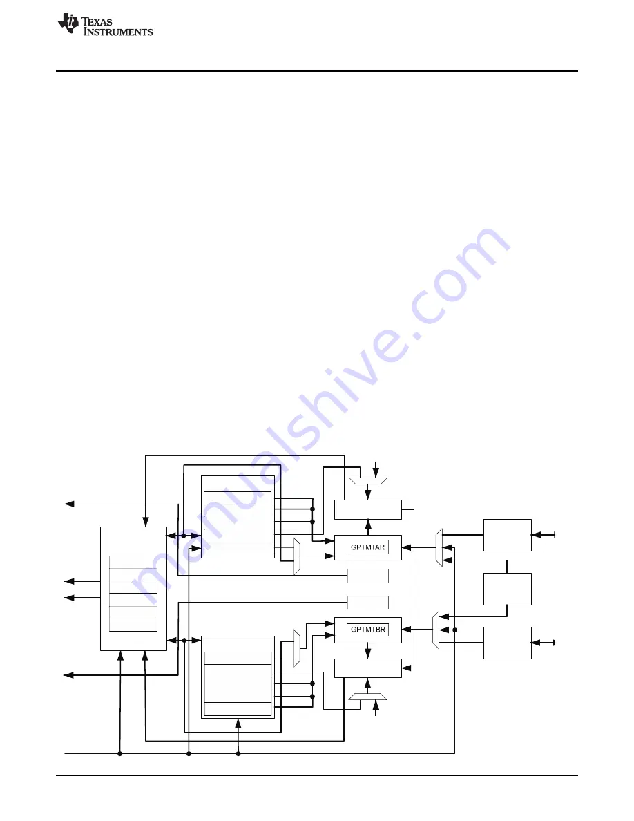
In the block diagram (
), the specific capture compare PWM (CCP) pins available depend on the
device. See
for the available CCP pins and their timer assignments.
Figure 2-1. GPTM Block Diagram


