Installing the Model 6C4 into the Rack Enclosure
Attention:
When installing this system drawer into a rack, ensure that a hazardous condition is not
created due to uneven mechanical loading. If your rack uses a stabilizer bar, it must be firmly attached
before installing or removing this system.
Choose one of the following system installation procedures. The installation procedure you choose
depends on the type of system rail assembly that was installed into your rack.
v
If your system rail assemblies are type 1, go to “Install the Model 6C4 onto a System Rail Assembly
(Type 1)”.
v
If your system rail assemblies are type 2, go to “Install the Model 6C4 onto a System Rail Assembly
(Type 2)” on page 582.
Install the Model 6C4 onto a System Rail Assembly (Type 1)
Attention:
When installing this unit in a rack, ensure that a hazardous condition is not created due to
uneven mechanical loading. If your rack uses a stabilizer bar, it must be firmly attached before installing or
removing this system.
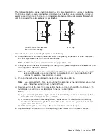
To install the Model 6C4 onto a system rail assembly (type 1), do the following:
1. Ensure both rails are in the retracted position in the rack.
2. Using three persons, grasp the two handles located on each side of the system drawer, and lift the
system drawer.
3. Place the system drawer on top of the retracted slide rails.
Note:
Built-in ledges located on each side of the system prevent the system from falling past the
slide rails.
4. Push the system all the way into the rack.
5. Pull the system out of the rack until you can see the second screw hole located on the inner rail.
Notice that the inner rails followed the system drawer out of the rack.
6. Align the second screw hole, located on the inner rail, with the second threaded screw hole, located
on the side of the system drawer. Secure the system drawer to the inner rail with M3 screws.
7. Align the front screw holes of each rail with the threaded screw holes on the system drawer. Secure
each screw hole with M3 screws.
8. To secure the third and fourth M3 retaining screws to the system, do the following:
a. Pull the system drawer from the rack.
Attention:
Do not
pull the system drawer out past the safety latches.
b. Align the rail to system retaining-screw access hole located on the middle rail to the third position
retaining screw hole located on the inner rail.
c. Secure an M3 screw into each rail’s third position retaining screw hole.
d. Align the rail to system retaining-screw access hole located on the middle rail to the fourth
position retaining screw hole located on the inner rail.
e. Secure an M3 screw into each rail’s fourth position retaining screw hole.
580
Eserver
pSeries 630 Model 6C4 and Model 6E4 Service Guide
Summary of Contents for @Server pSeries 630 6C4
Page 1: ...pSeries 630 Model 6C4 and Model 6E4 Service Guide SA38 0604 03 ERserver...
Page 2: ......
Page 3: ...pSeries 630 Model 6C4 and Model 6E4 Service Guide SA38 0604 03 ERserver...
Page 16: ...xiv Eserver pSeries 630 Model 6C4 and Model 6E4 Service Guide...
Page 18: ...xvi Eserver pSeries 630 Model 6C4 and Model 6E4 Service Guide...
Page 382: ...362 Eserver pSeries 630 Model 6C4 and Model 6E4 Service Guide...
Page 440: ...420 Eserver pSeries 630 Model 6C4 and Model 6E4 Service Guide...
Page 538: ...System Parts continued 518 Eserver pSeries 630 Model 6C4 and Model 6E4 Service Guide...
Page 541: ...Chapter 10 Parts Information 521...
Page 562: ...542 Eserver pSeries 630 Model 6C4 and Model 6E4 Service Guide...
Page 568: ...548 Eserver pSeries 630 Model 6C4 and Model 6E4 Service Guide...
Page 576: ...556 Eserver pSeries 630 Model 6C4 and Model 6E4 Service Guide...
Page 580: ...560 Eserver pSeries 630 Model 6C4 and Model 6E4 Service Guide...
Page 616: ...596 Eserver pSeries 630 Model 6C4 and Model 6E4 Service Guide...
Page 646: ...626 Eserver pSeries 630 Model 6C4 and Model 6E4 Service Guide...
Page 649: ......

