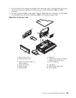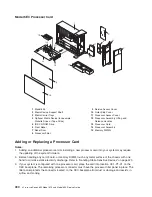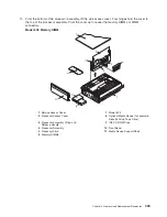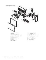
5. Replace the screws that secure the PCI riser card to the CEC backplane and chassis.
Note:
For proper alignment, insert all screws before tightening.
6. Reconnect the power, signal, and SCSI cables.
7. Replace all adapters to their proper locations as described in “Adding or Replacing a
Non-Hot-Pluggable PCI Adapter” on page 448.
8. Reconnect all of the labeled PCI adapter cables to their respective PCI adapters.
9. Replace the processor #2 assembly as described in “Adding or Replacing a Processor Card” on
page 490. If you removed a processor filler panel, replace the processor filler panel now.
10. Replace the media device support shelf. Tighten the thumbscrew located on the support shelf.
Note:
When replacing the support shelf, ensure that the lower support leg, located on the bottom
side of the support shelf, activates the microswitch located on the CEC backplane. Failure to
do so results in the system not being able to power on.
11. Replace all removed media drives, ensuring that the media drives removed are returned to the same
media bay locations from which they were removed. Refer to “Media Replacement” on page 469.
12. Reconnect all power and signal cables to their respective media drives.
13. Replace the front bezel as described in “Front Bezel Replacement (Model 6C4)” on page 442 or
“Front Bezel Replacement (Model 6E4)” on page 443.
14. Replace the service access cover as described in “Service Access Cover Replacement (Model 6C4)”
on page 431 or “Service Access Cover Replacement (Model 6E4)” on page 437.
15. Reconnect the power cables.
16. Replace the service access cover as described in “Service Access Cover Replacement (Model 6C4)”
on page 431 or “Service Access Cover Replacement (Model 6E4)” on page 437.
17. If you are servicing a Model 6C4, push the system drawer back into the operating position as
described in “Returning the Model 6C4 to the Operating Position” on page 430.
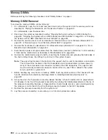
18. Set the I/O type to the required value as specified in 380.
19. Power on the system as described in “Starting the System without an HMC Attached” on page 425.
Note:
If you experience any problem when you boot the system, repeat substep 4, but the second
time, you must push harder.
20. If you are servicing a Model 6C4, close the rack doors.
If you are servicing a Model 6E4, close the bezel door.
Chapter 9. Removal and Replacement Procedures
479
Summary of Contents for @Server pSeries 630 6C4
Page 1: ...pSeries 630 Model 6C4 and Model 6E4 Service Guide SA38 0604 03 ERserver...
Page 2: ......
Page 3: ...pSeries 630 Model 6C4 and Model 6E4 Service Guide SA38 0604 03 ERserver...
Page 16: ...xiv Eserver pSeries 630 Model 6C4 and Model 6E4 Service Guide...
Page 18: ...xvi Eserver pSeries 630 Model 6C4 and Model 6E4 Service Guide...
Page 382: ...362 Eserver pSeries 630 Model 6C4 and Model 6E4 Service Guide...
Page 440: ...420 Eserver pSeries 630 Model 6C4 and Model 6E4 Service Guide...
Page 538: ...System Parts continued 518 Eserver pSeries 630 Model 6C4 and Model 6E4 Service Guide...
Page 541: ...Chapter 10 Parts Information 521...
Page 562: ...542 Eserver pSeries 630 Model 6C4 and Model 6E4 Service Guide...
Page 568: ...548 Eserver pSeries 630 Model 6C4 and Model 6E4 Service Guide...
Page 576: ...556 Eserver pSeries 630 Model 6C4 and Model 6E4 Service Guide...
Page 580: ...560 Eserver pSeries 630 Model 6C4 and Model 6E4 Service Guide...
Page 616: ...596 Eserver pSeries 630 Model 6C4 and Model 6E4 Service Guide...
Page 646: ...626 Eserver pSeries 630 Model 6C4 and Model 6E4 Service Guide...
Page 649: ......


