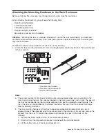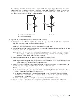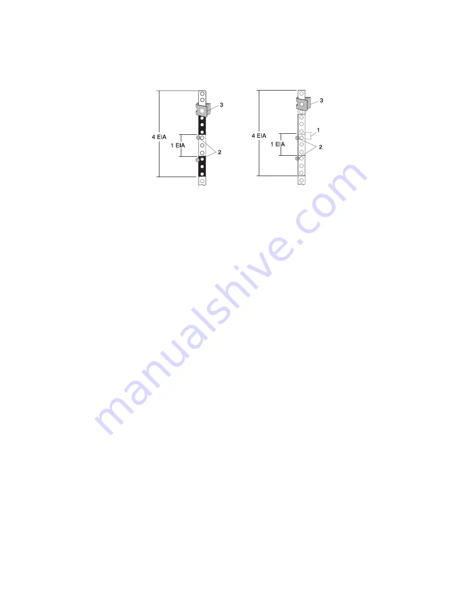
The following illustration shows one EIA unit and four EIA units. Depending on the rack manufacturer,
the EIA units may be separated either by color or by a line. Note that the holes along the rail are not
evenly spaced. If your rack has no color or line separation between EIA units, assume that each EIA
unit begins where the hole spacing is closest together.
1
Self-Adhesive Dot Placement
3
Nut Clip
2
EIA Unit Hole Spacing
5. If you do not have a rack-mounting template, do the following:
a. Determine where in the rack to place the system. The system you are about to install measures 4
EIA units high. Make note of the EIA location number.
Note:
An EIA unit on your rack consists of a grouping of three holes.
b. Facing the front of the rack and working from the right side, place a supplied self-adhesive dot next
to the top hole of the bottom EIA unit.
Note:
The self-adhesive dots are used to aid in identifying locations on the rack. If you no longer
have any of the dots, use some other form of marking tool to aid you in identifying hole
locations (for example, tape, a marker, or pencil).
c. Place another self-adhesive dot next to the top hole of the above EIA unit.
Note:
If you are counting the holes, begin with the hole identified by the first dot and count up four
holes. Place the second dot next to the fourth hole.
d. Secure a nut clip to the rack, four holes up from the top dot (bottom hole of the top EIA unit). The
nut clip aids in securing your system drawer to the rack while in transit.
Notes:
1) If you are counting the holes, begin with the hole identified by the first dot and count up four
holes. Place the nut clip next to the fourth hole.
2) Whenever a populated rack is being moved, secure the system drawers with two retaining
thumbscrews threaded through the nut clips. This action secures the system front bezel and
system chassis to the rack.
3) When counting from the nut clip to the bottom dot, there is an 8-hole span.
e. Repeat substeps a through d to the corresponding holes located on the left side of the rack.
Appendix D. Setting Up the System
571
Summary of Contents for @Server pSeries 630 6C4
Page 1: ...pSeries 630 Model 6C4 and Model 6E4 Service Guide SA38 0604 03 ERserver...
Page 2: ......
Page 3: ...pSeries 630 Model 6C4 and Model 6E4 Service Guide SA38 0604 03 ERserver...
Page 16: ...xiv Eserver pSeries 630 Model 6C4 and Model 6E4 Service Guide...
Page 18: ...xvi Eserver pSeries 630 Model 6C4 and Model 6E4 Service Guide...
Page 382: ...362 Eserver pSeries 630 Model 6C4 and Model 6E4 Service Guide...
Page 440: ...420 Eserver pSeries 630 Model 6C4 and Model 6E4 Service Guide...
Page 538: ...System Parts continued 518 Eserver pSeries 630 Model 6C4 and Model 6E4 Service Guide...
Page 541: ...Chapter 10 Parts Information 521...
Page 562: ...542 Eserver pSeries 630 Model 6C4 and Model 6E4 Service Guide...
Page 568: ...548 Eserver pSeries 630 Model 6C4 and Model 6E4 Service Guide...
Page 576: ...556 Eserver pSeries 630 Model 6C4 and Model 6E4 Service Guide...
Page 580: ...560 Eserver pSeries 630 Model 6C4 and Model 6E4 Service Guide...
Page 616: ...596 Eserver pSeries 630 Model 6C4 and Model 6E4 Service Guide...
Page 646: ...626 Eserver pSeries 630 Model 6C4 and Model 6E4 Service Guide...
Page 649: ......

