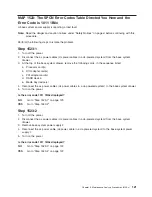
MAP 1521: Base System Drawer With Power Failure and No Error
Codes
Step 1521-1
For Model 6C4, do the following:
1. Place the drawer into the service position as described in “Placing the Model 6C4 into the Service
Position” on page 429.
2. Remove the service access cover as described in “Service Access Cover Removal (Model 6C4)” on
page 431.
For Model 6E4, do the following:
1. Place the deskside unit into a comfortable position for you to work on.
2. Remove the service access cover as described in “Service Access Cover Removal (Model 6E4)” on
page 436.
You may have been directed to this MAP for one or more of the following reasons:
v
The ac power supply power LEDs are not on. The power LEDs on the operator panel and the power
LEDs on the rear of the system unit are not blinking. The operator panel display is blank. Do the
following:
– Model 6C4, go to “Step 1521-2” on page 108.
– Model 6E4, go to “Step 1521-5” on page 109.
v
The ac power supply power LEDs are on. If equipped with dc power, the dc power supply power LEDs
are blinking. Power LEDs, for either ac or dc power supplies, on the operator panel and the rear of the
system unit are not blinking, and the operator panel display is blank. Go to “Step 1521-7” on page 110.
v
The ac power supply power LEDs are on. If equipped with dc power, the dc power LEDs are blinking.
Power LEDs located on the operator panel and the rear of the system unit are blinking, and
OK
is
displayed on the operator panel.
When the power button, located on the operator panel, is pressed:
– If equipped with dc power, the dc power LEDs, located on the power supplies, do not come on.
– The power LED (for either ac or dc powered systems), located on the operator panel, does not come
on.
– None of the cooling fans start to turn.
Go to “Step 1521-7” on page 110.
v
The ac power supply power LEDs are on. If equipped with dc power, the dc power supply power LEDs
are blinking. The power LED, located on the operator panel, is blinking and
OK
is displayed on the
operator panel.
When the power button on the operator panel is pressed:
– If equipped with dc power, the dc power LEDs on the power supplies come on.
– The power LED (for either ac or dc-powered systems), on the operator panel, comes on and all the
fans start to turn. However, the dc power LEDs located on the power supplies, and the power LED
located on the operator panel and the cooling fans do not stay on.
Go to “Step 1521-7” on page 110.
v
An SRN referenced in the
RS/6000
Eserver
pSeries Diagnostic Information for Multiple Bus Systems
is listed in MAP 1521 in the
″
Actions/Descriptions
″
column. Go to “Step 1521-11” on page 112.
Chapter 3. Maintenance Analysis Procedures (MAPs)
107
Summary of Contents for @Server pSeries 630 6C4
Page 1: ...pSeries 630 Model 6C4 and Model 6E4 Service Guide SA38 0604 03 ERserver...
Page 2: ......
Page 3: ...pSeries 630 Model 6C4 and Model 6E4 Service Guide SA38 0604 03 ERserver...
Page 16: ...xiv Eserver pSeries 630 Model 6C4 and Model 6E4 Service Guide...
Page 18: ...xvi Eserver pSeries 630 Model 6C4 and Model 6E4 Service Guide...
Page 382: ...362 Eserver pSeries 630 Model 6C4 and Model 6E4 Service Guide...
Page 440: ...420 Eserver pSeries 630 Model 6C4 and Model 6E4 Service Guide...
Page 538: ...System Parts continued 518 Eserver pSeries 630 Model 6C4 and Model 6E4 Service Guide...
Page 541: ...Chapter 10 Parts Information 521...
Page 562: ...542 Eserver pSeries 630 Model 6C4 and Model 6E4 Service Guide...
Page 568: ...548 Eserver pSeries 630 Model 6C4 and Model 6E4 Service Guide...
Page 576: ...556 Eserver pSeries 630 Model 6C4 and Model 6E4 Service Guide...
Page 580: ...560 Eserver pSeries 630 Model 6C4 and Model 6E4 Service Guide...
Page 616: ...596 Eserver pSeries 630 Model 6C4 and Model 6E4 Service Guide...
Page 646: ...626 Eserver pSeries 630 Model 6C4 and Model 6E4 Service Guide...
Page 649: ......


