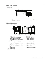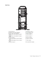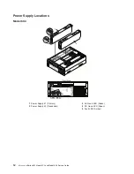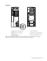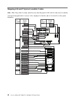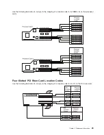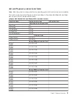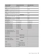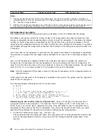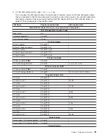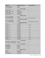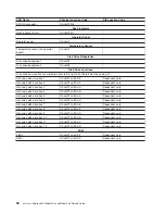
Location Codes
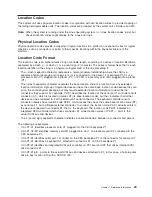
This system unit uses physical location codes in conjunction with AIX location codes to provide mapping of
the failing field replaceable units. The location codes are produced by the system unit’s firmware and AIX.
Note:
When the system is running under the Linux operating system, no
″
Linux location codes
″
exist, but
physical location codes might display in the Linux error logs.
Physical Location Codes
Physical location codes provide a mapping of logical functions in a platform (or expansion sites for logical
functions, such as connectors or ports) to their specific locations within the physical structure of the
platform.
Location Code Format
The location code is an alphanumeric string of variable length, consisting of a series of location identifiers,
separated by a dash (-), or slash (/), or a pound sign (#) character. The series is hierarchical; that is, each
location identifier in the string is a physical or logical child of the one preceding it.
v
The - (dash) separator character represents a normal structural relationship where the child is a
separate physical package and it plugs into (or is connected to) the parent. For example, P1-C1 is a
processor card (C1) plugged into a planar (P1), or P1-M1 is a memory card (M1) plugged into a planar
(P1).
v
The / (slash) separator character separates the base location code of a function from any extended
location information. A group of logical devices can have the same base location code because they are
all on the same physical package, but may require extended location information to describe the
connectors they support. For example, P2/S1 describes the location of the serial port 1 controller and its
connector (S1), which is located on planar P2 (its base location code), but the / indicates that further
devices can be connected to it at the external S1 serial connector. The keyboard controller and its
connector likewise have location code P2/K1, which means they have the same base location code (P2)
as serial port 1, but a different external connector. In contrast, the location code P2-K1 actually points to
the device connected to connector K1; that is, the keyboard. The location code P2/Z1 indicates an
integrated SCSI controller which drives connector Z1, while location codes of P2-Z1-... point to the
actual SCSI bus and devices.
v
The # (pound sign) separator character indicates a cable connection between a connector and parent.
The following are examples:
v
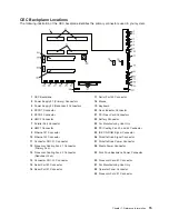
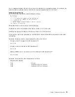
U0.1-P1-C1 identifies processor card C1 plugged into the CEC backplane P1.
v
U0.1-P1-C2-M1 identifies memory card M1 plugged into slot 1 on processor card C2 connected to the
CEC backplane P1.
v
U0.1-P1/S1 identifies serial port 1 controller on the CEC backplane P1 or the connector for serial port 1.
v
U0.1-P1-K1 identifies a keyboard K1, attached to connector K1 on CEC backplane P1.
v
U0.1-P2/Z1 identifies an integrated SCSI port controller on PCI riser card P2 that drives internal SCSI
drive connector Z1.
v
U0.1-P2-Z1-A8... points to the actual SCSI bus and devices attached to Z1; in this case, a hot-plug disk
drive in bay location D10 with a SCSI ID of 8.
Chapter 1. Reference Information
23
Summary of Contents for @Server pSeries 630 6C4
Page 1: ...pSeries 630 Model 6C4 and Model 6E4 Service Guide SA38 0604 03 ERserver...
Page 2: ......
Page 3: ...pSeries 630 Model 6C4 and Model 6E4 Service Guide SA38 0604 03 ERserver...
Page 16: ...xiv Eserver pSeries 630 Model 6C4 and Model 6E4 Service Guide...
Page 18: ...xvi Eserver pSeries 630 Model 6C4 and Model 6E4 Service Guide...
Page 382: ...362 Eserver pSeries 630 Model 6C4 and Model 6E4 Service Guide...
Page 440: ...420 Eserver pSeries 630 Model 6C4 and Model 6E4 Service Guide...
Page 538: ...System Parts continued 518 Eserver pSeries 630 Model 6C4 and Model 6E4 Service Guide...
Page 541: ...Chapter 10 Parts Information 521...
Page 562: ...542 Eserver pSeries 630 Model 6C4 and Model 6E4 Service Guide...
Page 568: ...548 Eserver pSeries 630 Model 6C4 and Model 6E4 Service Guide...
Page 576: ...556 Eserver pSeries 630 Model 6C4 and Model 6E4 Service Guide...
Page 580: ...560 Eserver pSeries 630 Model 6C4 and Model 6E4 Service Guide...
Page 616: ...596 Eserver pSeries 630 Model 6C4 and Model 6E4 Service Guide...
Page 646: ...626 Eserver pSeries 630 Model 6C4 and Model 6E4 Service Guide...
Page 649: ......

