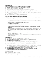
Step 1542-17
1. Turn off the power.
2. At the base system, reconnect the cable connection at RIO-2 port 0 (U0.1-P1/Q2) recorded in “Step
1542-7” on page 131.
3. At the base system, reconnect the cable connection at RIO-2 port 1 (U0.1-P1/Q3) recorded in “Step
1542-7” on page 131.
4. Reconnect the power cables to the I/O subsystems that were found attached to the base system RIO-2
ports mentioned in substeps 2 and 3 above. All I/O subsystems that were attached to the base system
RIO-2 port 0 (U0.1-P1/Q2) and RIO-2 port 1 (U0.1-P1/Q3) should now be physically reconnected to
the base system.
5. Make sure the I/O subsystem(s) are cabled correctly as shown in “Subsystem Positioning and Cabling”
on page 41.
6. Turn on the power to boot standalone diagnostics from CD.
7. If the Please define the System Console screen is displayed, follow directions to select the system
console.
8. Use the Display Configuration and Resource List to list all attached devices and adapters (refer to the
RS/6000
Eserver
pSeries Diagnostic Information for Multiple Bus Systems
, if necessary).
9. Check that all attached devices and adapters are listed.
Did the Please define the System Console screen display and are all attached devices and adapters
listed?
NO
Go to “Step 1542-9” on page 131 to isolate I/O problems attached to the base system RIO-2
connectors.
YES
The symptom has changed. No items were replaced. Go to “Step 1542-16” on page 134.
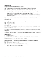
Step 1542-18
Are there any adapters in slots 1, 2, 3, or 4 (location codes U0.1-P1-I1 through I4) in the base
system?
NO
Go to “Step 1542-19”.
YES
Go to “Step 1542-21” on page 136.
Step 1542-19
Replace the CEC backplane, location U0.1-P1
Step 1542-20
1. Boot standalone diagnostics from CD.
2. If the Please define the System Console screen is displayed, follow directions to select the system
console.
3. Use the Display Configuration and Resource List to list all attached devices and adapters (refer to the
RS/6000
Eserver
pSeries Diagnostic Information for Multiple Bus Systems
, order number SA38-0509,
if necessary).
4. Check that all attached devices and adapters are listed.
Did the Please define the System Console screen display and are all attached devices and adapters
listed?
NO
Go to “Step 1542-24” on page 137.
YES
Go to “Step 1542-16” on page 134.
Chapter 3. Maintenance Analysis Procedures (MAPs)
135
Summary of Contents for @Server pSeries 630 6C4
Page 1: ...pSeries 630 Model 6C4 and Model 6E4 Service Guide SA38 0604 03 ERserver...
Page 2: ......
Page 3: ...pSeries 630 Model 6C4 and Model 6E4 Service Guide SA38 0604 03 ERserver...
Page 16: ...xiv Eserver pSeries 630 Model 6C4 and Model 6E4 Service Guide...
Page 18: ...xvi Eserver pSeries 630 Model 6C4 and Model 6E4 Service Guide...
Page 382: ...362 Eserver pSeries 630 Model 6C4 and Model 6E4 Service Guide...
Page 440: ...420 Eserver pSeries 630 Model 6C4 and Model 6E4 Service Guide...
Page 538: ...System Parts continued 518 Eserver pSeries 630 Model 6C4 and Model 6E4 Service Guide...
Page 541: ...Chapter 10 Parts Information 521...
Page 562: ...542 Eserver pSeries 630 Model 6C4 and Model 6E4 Service Guide...
Page 568: ...548 Eserver pSeries 630 Model 6C4 and Model 6E4 Service Guide...
Page 576: ...556 Eserver pSeries 630 Model 6C4 and Model 6E4 Service Guide...
Page 580: ...560 Eserver pSeries 630 Model 6C4 and Model 6E4 Service Guide...
Page 616: ...596 Eserver pSeries 630 Model 6C4 and Model 6E4 Service Guide...
Page 646: ...626 Eserver pSeries 630 Model 6C4 and Model 6E4 Service Guide...
Page 649: ......

