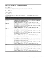
MAP 154C: SPCN Cable Problem Isolation
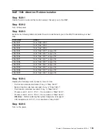
Step 154C-1
Record the error code, location code(s), and word 13 that sent you to this MAP.
Step 154C-2
Turn off the power.
Step 154C-3
Locate the word 13 value that you recorded in Step 154C-1 in the following table and perform the
indicated action.
Word 13 Value
Action
A780 xxxx
Replace the SPCN cable attached to U0.1-P1/Q4 of the base system drawer.
A781 xxxx
1. Trace the SPCN cable attached to U0.1-P1/Q4 of the base system drawer back to an
attached I/O drawer connector U0.
dd
-P1/Q5.
2. Replace the SPCN cable attached to connector U0.
dd
-P1/Q6 of this I/O drawer.
A782 xxxx
1. Trace the SPCN cable attached to U0.1-P1/Q4 of the base system drawer back to an
attached I/O drawer connector U0.
dd
-P1/Q5.
2. Trace the SPCN cable attached to connector U0.
dd
-P1/Q6 of this I/O drawer back to an
attached I/O drawer connector U0.
dd
-P1/Q5.
3. Replace the SPCN cable attached to connector U0.
dd
-P1/Q6 of this I/O drawer.
A783 xxxx
1. Trace the SPCN cable attached to U0.1-P1/Q4 of the base system drawer back to an
attached I/O drawer connector U0.
dd
-P1/Q5.
2. Trace the SPCN cable attached to connector U0.
dd
-P1/Q6 of this I/O drawer back to an
attached I/O drawer connector U0.
dd
-P1/Q5.
3. Trace the SPCN cable attached to connector U0.
dd
-P1/Q6 of this I/O drawer back to an
attached I/O drawer connector U0.
dd
-P1/Q5.
4. Replace the SPCN cable attached to connector U0.
dd
-P1/Q6 of this I/O drawer.
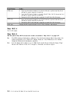
A784 xxxx
1. Trace the SPCN cable attached to U0.1-P1/Q4 of the base system drawer back to an
attached I/O drawer connector U0.
dd
-P1/Q5.
2. Trace the SPCN cable attached to connector U0.
dd
-P1/Q6 of this I/O drawer back to an
attached I/O drawer connector U0.
dd
-P1/Q5.
3. Trace the SPCN cable attached to connector U0.
dd
-P1/Q6 of this I/O drawer back to an
attached I/O drawer connector U0.
dd
-P1/Q5.
4. Trace the SPCN cable attached to connector U0.
dd
-P1/Q6 of this I/O drawer back to an
attached I/O drawer connector U0.
dd
-P1/Q5.
5. Replace the SPCN cable attached to connector U0.
dd
-P1/Q6 of this I/O drawer.
A785 xxxx
1. Trace the SPCN cable attached to U0.1-P1/Q5 of the base system drawer back to an
attached I/O drawer connector U0.
dd
-P1/Q6.
2. Trace the SPCN cable attached to connector U0.
dd
-P1/Q5 of this I/O drawer back to an
attached I/O drawer connector U0.
dd
-P1/Q6.
3. Trace the SPCN cable attached to connector U0.
dd
-P1/Q5 of this I/O drawer back to an
attached I/O drawer connector U0.
dd
-P1/Q6.
4. Replace the SPCN cable attached to connector U0.
dd
-P1/Q5 of this I/O drawer.
Chapter 3. Maintenance Analysis Procedures (MAPs)
157
Summary of Contents for @Server pSeries 630 6C4
Page 1: ...pSeries 630 Model 6C4 and Model 6E4 Service Guide SA38 0604 03 ERserver...
Page 2: ......
Page 3: ...pSeries 630 Model 6C4 and Model 6E4 Service Guide SA38 0604 03 ERserver...
Page 16: ...xiv Eserver pSeries 630 Model 6C4 and Model 6E4 Service Guide...
Page 18: ...xvi Eserver pSeries 630 Model 6C4 and Model 6E4 Service Guide...
Page 382: ...362 Eserver pSeries 630 Model 6C4 and Model 6E4 Service Guide...
Page 440: ...420 Eserver pSeries 630 Model 6C4 and Model 6E4 Service Guide...
Page 538: ...System Parts continued 518 Eserver pSeries 630 Model 6C4 and Model 6E4 Service Guide...
Page 541: ...Chapter 10 Parts Information 521...
Page 562: ...542 Eserver pSeries 630 Model 6C4 and Model 6E4 Service Guide...
Page 568: ...548 Eserver pSeries 630 Model 6C4 and Model 6E4 Service Guide...
Page 576: ...556 Eserver pSeries 630 Model 6C4 and Model 6E4 Service Guide...
Page 580: ...560 Eserver pSeries 630 Model 6C4 and Model 6E4 Service Guide...
Page 616: ...596 Eserver pSeries 630 Model 6C4 and Model 6E4 Service Guide...
Page 646: ...626 Eserver pSeries 630 Model 6C4 and Model 6E4 Service Guide...
Page 649: ......

