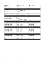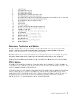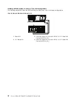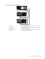
Dimensions
Rack (Model 6C4)
Tower (Model 6E4)
Install/Air Flow
Maintenance of proper service clearance should allow proper airflow.
Service
When installing a rack unit, refer to “System Service Clearances” on
page 563 for the rack correct clearances.
1. Inrush currents occur only at initial application of power, no inrush occurs during normal power off-on cycle.
2. The upper limit of the dry bulb temperature must be derated 1 degree C per 137 m (450 ft.) above 915 m (3000
ft.).
3. The upper limit of the wet bulb temperature must be derated 1 degree C per 274 m (900 ft. ) above 305 m (1000
ft.).
4. Levels are for a single system installed in a T00 32-EIA rack with the center of the unit approximately 1500 mm
(59 in.) off the floor.
External AC Power Cables
To avoid electrical shock, a power cable with a grounded attachment plug is provided. Use only properly
grounded outlets.
Power cables used in the United States and Canada are listed by Underwriter’s Laboratories (UL) and
certified by the Canadian Standards Association (CSA). These power cords consist of the following:
v
Electrical cables, Type SVT or SJT.
v
Attachment plugs complying with National Electrical Manufacturers Association (NEMA) 5-15P, that is:
″
For 115 V operation, use a UL listed cable set consisting of a minimum 14 AWG, Type SVT or SJT
three-conductor cord a maximum of 15 feet in length and a parallel blade, grounding type attachment plug
rated at 15 A, 125 V.
″
″
For 230 V operation in the United States use a UL listed cable set consisting of a minimum 18 AWG,
Type SVT or SJT three-conductor cable a maximum of 15 feet in length, and a tandem blade, grounding
type attachment plug rated at 15 A, 250 V.
″
v
Appliance couplers complying with International Electrotechnical Commission (IEC) Standard 320, Sheet
C13.
Power cables used in other countries consist of the following:
v
Electrical cables, Type HD21.
v
Attachment plugs approved by the appropriate testing organization for the specific countries where they
are used.
″
For units set at 230 V (outside of U.S.): use a cable set consisting of a minimum 18 AWG (1.0 mm
2
nominal cross sectional area). Outside of North America , a more common cordage reference is in mm
2
and for a HAR (harmonized) cord, you may not find a AWG equivalent.
To find the power cables that are available, refer to Chapter 10, “Parts Information”, on page 515.
Chapter 1. Reference Information
47
Summary of Contents for @Server pSeries 630 6C4
Page 1: ...pSeries 630 Model 6C4 and Model 6E4 Service Guide SA38 0604 03 ERserver...
Page 2: ......
Page 3: ...pSeries 630 Model 6C4 and Model 6E4 Service Guide SA38 0604 03 ERserver...
Page 16: ...xiv Eserver pSeries 630 Model 6C4 and Model 6E4 Service Guide...
Page 18: ...xvi Eserver pSeries 630 Model 6C4 and Model 6E4 Service Guide...
Page 382: ...362 Eserver pSeries 630 Model 6C4 and Model 6E4 Service Guide...
Page 440: ...420 Eserver pSeries 630 Model 6C4 and Model 6E4 Service Guide...
Page 538: ...System Parts continued 518 Eserver pSeries 630 Model 6C4 and Model 6E4 Service Guide...
Page 541: ...Chapter 10 Parts Information 521...
Page 562: ...542 Eserver pSeries 630 Model 6C4 and Model 6E4 Service Guide...
Page 568: ...548 Eserver pSeries 630 Model 6C4 and Model 6E4 Service Guide...
Page 576: ...556 Eserver pSeries 630 Model 6C4 and Model 6E4 Service Guide...
Page 580: ...560 Eserver pSeries 630 Model 6C4 and Model 6E4 Service Guide...
Page 616: ...596 Eserver pSeries 630 Model 6C4 and Model 6E4 Service Guide...
Page 646: ...626 Eserver pSeries 630 Model 6C4 and Model 6E4 Service Guide...
Page 649: ......

