Hot-Swap Fan Assembly Removal
This section contains procedures for removing processor cooling fans and PCI adapter cooling fans. Select
the removal procedure according to the hot-swap fan assembly that you are servicing.
Note:
On systems with Linux installed, you might be required to shut down and run AIX diagnostics to
verify the hot-swap fan repair.
To remove a hot-swap fan, do the following:
1. On a Model 6C4, open the front and rear rack doors and place the system into the service position as
described in “Placing the Model 6C4 into the Service Position” on page 429.
On a Model 6E4, open the bezel door.
2. Remove the service access cover as described in “Service Access Cover Removal (Model 6C4)” on
page 431 or “Service Access Cover Removal (Model 6E4)” on page 436.
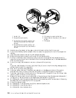
3. Locate the cooling fan assemblies, as shown in the following illustration.
4. The failing fan assembly has the amber-colored LED that is lit.
Note:
All of the hot-swap fan assemblies used in your system have an amber-colored LED located on
the top of the fan assembly. When lit, this LED indicates that its fan assembly has a problem.
The fan might not be spinning or is not spinning fast enough to help cool the system unit.
Hot-Swap Processor Fan Removal
If you are servicing one of the processor cooling fan assemblies, do the following:
1. Lift the processor fan access cover.
2. Place your thumb and index finger into the two finger holes, located on the top of the faulty fan.
3. Lift the faulty fan out of the system.
Notes:
a. The processor cooling fans have a docking connector, located on the bottom of the fan assembly.
The docking connectors automatically disconnect as the fan is being removed from the chassis.
b. Unless you are performing a hot-swap removal or replacement of the processor fans, keep the
processor fan access cover closed.
Hot-Swap PCI Adapter Fan Removal
Attention:
The system will power off if the failing PCI cooling fan has not been exchanged within five
minutes.
If you are servicing one of the PCI adapter cooling fan assemblies, do the following:
1. Disconnect the cooling fan’s power cable from the connector, located on the front of the fan assembly.
2. Place your index finger below the front connector and slide the fan out of the fan cage.
Note:
The adapter cooling fan assemblies are arranged in stacked pairs. You cannot replace a single
fan in the stacked pair.
462
Eserver
pSeries 630 Model 6C4 and Model 6E4 Service Guide
Summary of Contents for @Server pSeries 630 6C4
Page 1: ...pSeries 630 Model 6C4 and Model 6E4 Service Guide SA38 0604 03 ERserver...
Page 2: ......
Page 3: ...pSeries 630 Model 6C4 and Model 6E4 Service Guide SA38 0604 03 ERserver...
Page 16: ...xiv Eserver pSeries 630 Model 6C4 and Model 6E4 Service Guide...
Page 18: ...xvi Eserver pSeries 630 Model 6C4 and Model 6E4 Service Guide...
Page 382: ...362 Eserver pSeries 630 Model 6C4 and Model 6E4 Service Guide...
Page 440: ...420 Eserver pSeries 630 Model 6C4 and Model 6E4 Service Guide...
Page 538: ...System Parts continued 518 Eserver pSeries 630 Model 6C4 and Model 6E4 Service Guide...
Page 541: ...Chapter 10 Parts Information 521...
Page 562: ...542 Eserver pSeries 630 Model 6C4 and Model 6E4 Service Guide...
Page 568: ...548 Eserver pSeries 630 Model 6C4 and Model 6E4 Service Guide...
Page 576: ...556 Eserver pSeries 630 Model 6C4 and Model 6E4 Service Guide...
Page 580: ...560 Eserver pSeries 630 Model 6C4 and Model 6E4 Service Guide...
Page 616: ...596 Eserver pSeries 630 Model 6C4 and Model 6E4 Service Guide...
Page 646: ...626 Eserver pSeries 630 Model 6C4 and Model 6E4 Service Guide...
Page 649: ......

