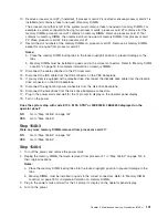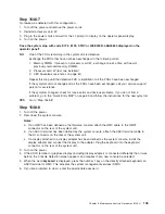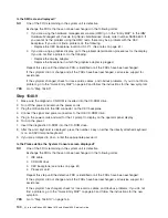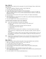
MAP 154B: Insufficient Hardware Resources Problem Isolation
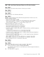
Step 154B-1
Record the error code, location code(s) and word 13 that sent you to this MAP.
Step 154B-2
Turn off the power.
Step 154B-3
Make sure the power is off on the base system drawer.
Step 154B-4
Attention:
Before replacing any parts, examine the base system drawer for violation of any of the
following configuration constraints.
v
At least one 1-way processor is installed.
v
At least one quad of DIMMs is installed on any of the installed processor cards at locations:
U0.1-P1-Cx-My, where x is 1 or 2 and y is 1, 3, 6, and 8 on the same processor card.
v
Quads are populated in DIMM slots 1, 3, 6, 8 first, and then in slots 2, 4, 5, 7
Replace the following cards, if present, one at a time:
v
First location code item recorded, if any, in “Step 154B-1”.
v
Second location code item recorded, if any, in “Step 154B-1”.
v
Third location code item recorded, if any, in “Step 154B-1”.
v
If the value of word 13, recorded in “Step 154B-1”, is 402F0000, 403F0000, or 40FF0000, replace the
following, if installed:
– Processor card 1 at location U0.1-P1-C1, if not recorded in “Step 154B-1”.
– Processor card 2 at location U0.1-P1-C2, if not recorded in “Step 154B-1”.
v
If the value of word 13, recorded in “Step 154B-1”, is 40600000, replace the processor backplane at
U0.1-P1, if not recorded in “Step 154B-1”.
v
If the value of word 13, recorded in “Step 154B-1”, is 41100000, replace the processor backplane at
U0.1-P1, if not recorded in “Step 154B-1”.
v
Memory DIMMs at locations U0.1-P1-C1-M1, M3, M6, M8, if not recorded in “Step 154B-1”.
v
Memory DIMMs at locations U0.1-P1-C1-M2, M4, M5, M7, if not recorded in “Step 154B-1”.
v
Processor backplane at U0.1-P1, if not recorded in “Step 154B-1”.
Step 154B-5
Turn on the power.
Step 154B-6
Did the system stop with the same error code as recorded in “Step 154B-1”?
No
The card just replaced was defective.
This ends the procedure.
Go to
″
MAP 0410: Repair Checkout
″
in the
RS/6000
Eserver
pSeries Diagnostic Information for
Multiple Bus Systems
.
Yes
Go to “Step 154B-7” on page 156.
Chapter 3. Maintenance Analysis Procedures (MAPs)
155
Summary of Contents for @Server pSeries 630 6C4
Page 1: ...pSeries 630 Model 6C4 and Model 6E4 Service Guide SA38 0604 03 ERserver...
Page 2: ......
Page 3: ...pSeries 630 Model 6C4 and Model 6E4 Service Guide SA38 0604 03 ERserver...
Page 16: ...xiv Eserver pSeries 630 Model 6C4 and Model 6E4 Service Guide...
Page 18: ...xvi Eserver pSeries 630 Model 6C4 and Model 6E4 Service Guide...
Page 382: ...362 Eserver pSeries 630 Model 6C4 and Model 6E4 Service Guide...
Page 440: ...420 Eserver pSeries 630 Model 6C4 and Model 6E4 Service Guide...
Page 538: ...System Parts continued 518 Eserver pSeries 630 Model 6C4 and Model 6E4 Service Guide...
Page 541: ...Chapter 10 Parts Information 521...
Page 562: ...542 Eserver pSeries 630 Model 6C4 and Model 6E4 Service Guide...
Page 568: ...548 Eserver pSeries 630 Model 6C4 and Model 6E4 Service Guide...
Page 576: ...556 Eserver pSeries 630 Model 6C4 and Model 6E4 Service Guide...
Page 580: ...560 Eserver pSeries 630 Model 6C4 and Model 6E4 Service Guide...
Page 616: ...596 Eserver pSeries 630 Model 6C4 and Model 6E4 Service Guide...
Page 646: ...626 Eserver pSeries 630 Model 6C4 and Model 6E4 Service Guide...
Page 649: ......

