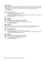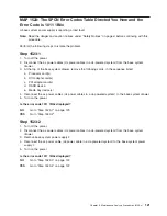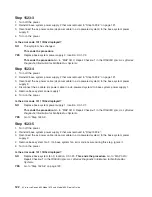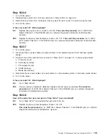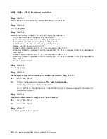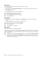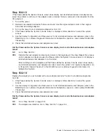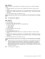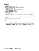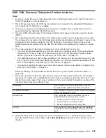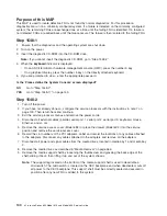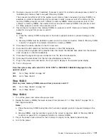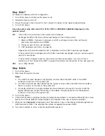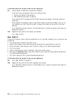
Step 1542-15
1. Turn off the power.
2. Disconnect the I/O subsystem power cables.
3. Replace the following parts, one at a time, in the sequence listed:
a. RIO adapter (if present) of any
″
looped one
″
I/O subsystem attached to the base system.
b. I/O subsystem backplane of any
″
looped one
″
I/O subsystem attached to the base system.
c. RIO adapter (if present) of any
″
looped two
″
I/O subsystem attached to the base system.
d. I/O subsystem backplane of any
″
looped two
″
I/O subsystem attached to the base system.
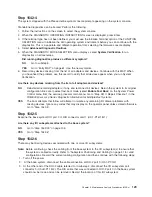
4. Reconnect the I/O subsystem power cables.
5. Turn on the power.
6. Boot standalone diagnostics from CD.
7. If the Please define the System Console screen is displayed, follow directions to select the system
console.
8. Use the Display Configuration and Resource List to list all attached devices and adapters (refer to the
RS/6000
Eserver
pSeries Diagnostic Information for Multiple Bus Systems
, order number SA38-0509
if necessary).
9. Check that all attached devices and adapters are listed.
Did the Please define the System Console screen display and are all attached devices and adapters
listed?
NO
Replace the next part in the list and return to the beginning of this step. Repeat this process until
a part causes the Please define the System Console screen to be displayed and all attached
devices and adapters to be listed. If you have replaced all the items listed above and the Please
define the System Console screen does not display or all attached devices and adapters are not
listed, check any external devices and cabling. If you do not find a problem, contact your next level
of support for assistance.
YES
Go to “Step 1542-16”.
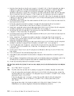
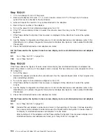
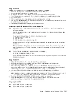
Step 1542-16
1. Turn off the power.
2. The item just replaced fixed the problem.
3. If a display adapter with keyboard and mouse were used, reinstall the display adapter card, keyboard,
and mouse.
4. Reconnect the diskette drive cable to the diskette drive connector on the base system.
5. Reconnect the tape drive (if previously installed) to the internal SCSI bus cable.
6. Plug in all adapters that were previously removed but not reinstalled.
7. Reconnect the I/O subsystem power cables that were previously disconnected.
Reconfigure the system to its original condition. Go to “Map 0410: Repair Checkout” in the
RS/6000
Eserver
pSeries Diagnostic Information for Multiple Bus Systems
.
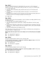
134
Eserver
pSeries 630 Model 6C4 and Model 6E4 Service Guide
Summary of Contents for @Server pSeries 630 6C4
Page 1: ...pSeries 630 Model 6C4 and Model 6E4 Service Guide SA38 0604 03 ERserver...
Page 2: ......
Page 3: ...pSeries 630 Model 6C4 and Model 6E4 Service Guide SA38 0604 03 ERserver...
Page 16: ...xiv Eserver pSeries 630 Model 6C4 and Model 6E4 Service Guide...
Page 18: ...xvi Eserver pSeries 630 Model 6C4 and Model 6E4 Service Guide...
Page 382: ...362 Eserver pSeries 630 Model 6C4 and Model 6E4 Service Guide...
Page 440: ...420 Eserver pSeries 630 Model 6C4 and Model 6E4 Service Guide...
Page 538: ...System Parts continued 518 Eserver pSeries 630 Model 6C4 and Model 6E4 Service Guide...
Page 541: ...Chapter 10 Parts Information 521...
Page 562: ...542 Eserver pSeries 630 Model 6C4 and Model 6E4 Service Guide...
Page 568: ...548 Eserver pSeries 630 Model 6C4 and Model 6E4 Service Guide...
Page 576: ...556 Eserver pSeries 630 Model 6C4 and Model 6E4 Service Guide...
Page 580: ...560 Eserver pSeries 630 Model 6C4 and Model 6E4 Service Guide...
Page 616: ...596 Eserver pSeries 630 Model 6C4 and Model 6E4 Service Guide...
Page 646: ...626 Eserver pSeries 630 Model 6C4 and Model 6E4 Service Guide...
Page 649: ......

